



‹
›
‹
›
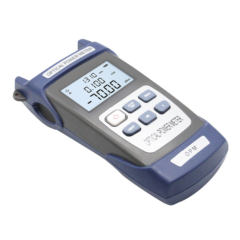
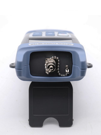
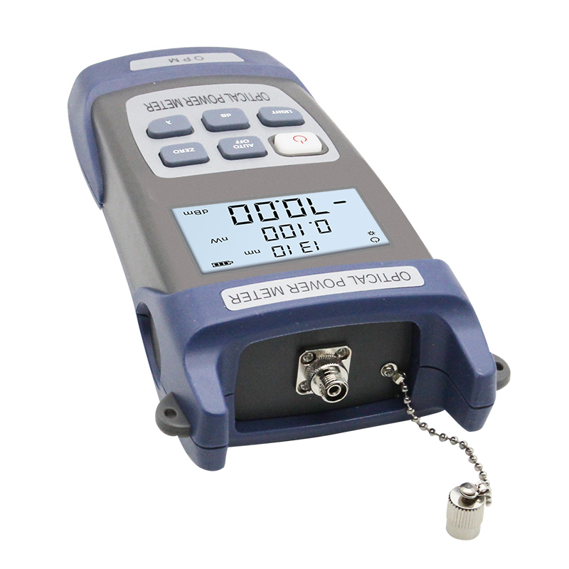
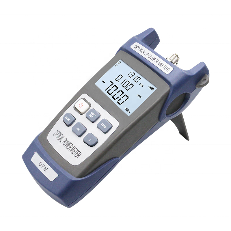
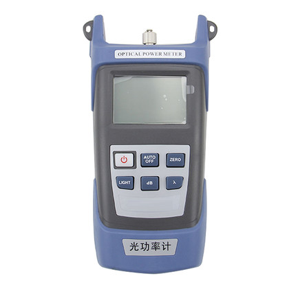
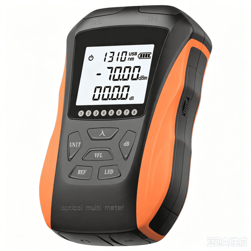
LF059 Handheld Fiber Optic Power Meter FTTH Network Cable Tester
Share on





Handheld Fiber Optic Power Meter for FTTH Signal and Loss Testing
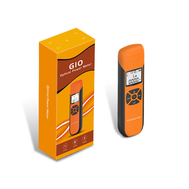
Handheld fiber optic power meter measures absolute optical power in dBm and relative change in dB for FTTH activation, maintenance and passive-link verification. The instrument is intended for contractors, ISP field teams, distributors and project owners who need a repeatable way to confirm received power, compare link loss and identify whether a result is within the network acceptance budget.
A power meter does not identify the distance to a splice, bend or break. For insertion-loss testing it must be paired with a stable optical light source at the same wavelength; for event location and trace analysis, use an OTDR. LinkFiber can configure the measurement range, connector adapters, wavelength set, accessories, label, manual and packing against an approved order specification.
Where This Optical Power Meter Fits in the Test Workflow
How to Obtain a Defensible Loss Result
First select the test wavelength that matches the service or acceptance method. Clean and inspect the source port, meter adapter and reference cords. Connect the light source directly to the meter through the approved reference cord, allow the source to stabilize, then store the reference level. Insert the link under test without changing the reference cord geometry, and record the loss in dB. If adapters or reference cords are changed, establish a new reference.
For installed single-mode cabling, IEC 61280-4-2 describes attenuation and optical-return-loss measurement principles. IEC 61315 addresses calibration of fibre-optic power meters. Mentioning these standards does not by itself prove compliance: a B2B buyer should request the calibration status, reference conditions, uncertainty statement and report scope for the exact ordered instrument.
Technical Specifications
Configuration control: The table above is retained as the product specification reference. Measuring range, supported calibration wavelengths, adapter set, accuracy, protection rating and package contents must be reconfirmed on the quotation and approved sample because optional versions are not interchangeable. A displayed resolution of 0.01 dB is not the same as total measurement accuracy or calibration uncertainty.
Measurement Limits Buyers Should Understand
- Wavelength mismatch: a meter may display a number at the wrong wavelength, but the detector calibration factor will be wrong and the result may not be suitable for acceptance.
- Range and saturation: choose the low-level telecom range for access-network sensitivity or the high-power range for CATV/EDFA work. Never assume one model safely covers both.
- Connector geometry: the adapter must mechanically fit the connector and the test cord polish must match the equipment port. Do not directly mate UPC and APC end faces.
- Reference quality: dirty or unstable reference cords can consume more error budget than the device resolution suggests.
- Absolute power versus insertion loss: dBm is an absolute power level; dB is a relative loss or gain. The project report must state which value is being accepted.
Common Field-Failure Risks and Prevention
Pre-shipment Quality and Acceptance Plan
- Verify the ordered measurement range, detector type, wavelength set, connector adapters, battery version and accessories.
- Check zero response, wavelength switching, dBm/dB display, reference storage, backlight and auto-off functions.
- Compare readings at agreed wavelengths and power points against a controlled reference instrument; record the permissible deviation.
- Inspect optical ports and adapters, clean where required, and protect every port with a dust cap.
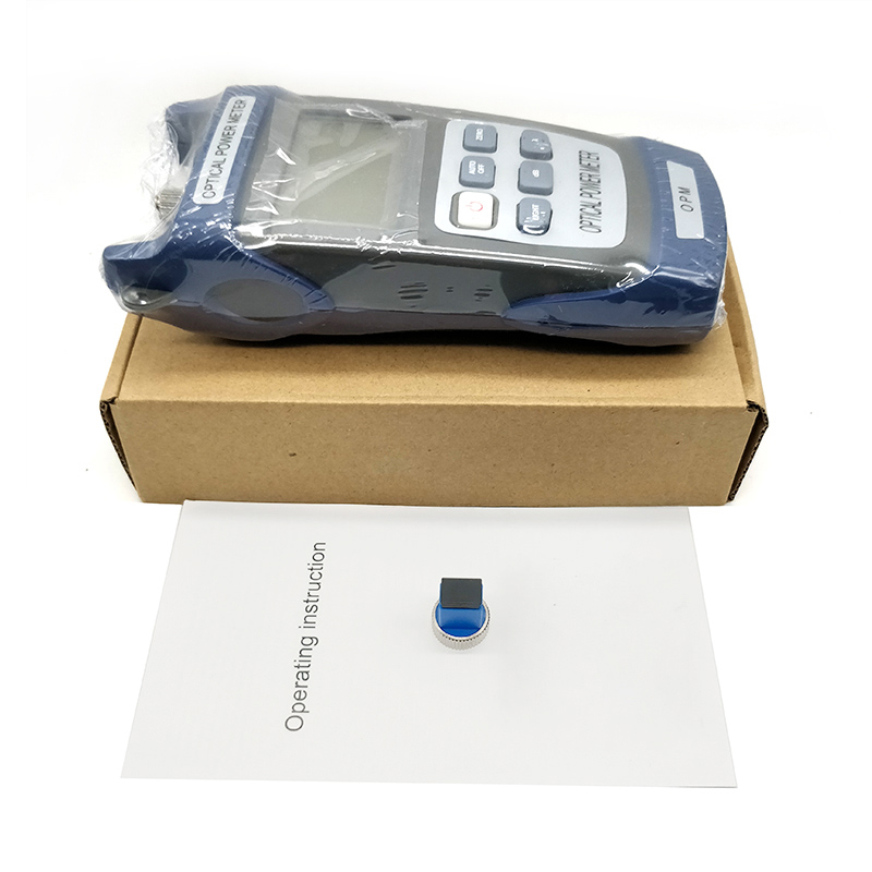
- Confirm serial number, label, manual language, calibration/report request, quantity and packing list before shipment.
B2B Buyer Guide: Information Required for an Accurate Quote
- Application: FTTH activation, passive-link loss, CATV/high-power measurement, component QC or maintenance.
- Required power range and typical expected signal level; choose between standard low-level and high-power variants.
- Single-mode or multimode network, required wavelengths and whether frequency/tone identification is needed.
- Connector types and polish at the source and link: SC, FC, ST, LC, UPC or APC; specify required adapters.
- Required calibration certificate, acceptance uncertainty, serial-number traceability and report format.
- Battery preference, carrying case, cleaning kit, light source, reference cords, label, language and destination plug requirements.
When to Choose Another Fiber Test Instrument
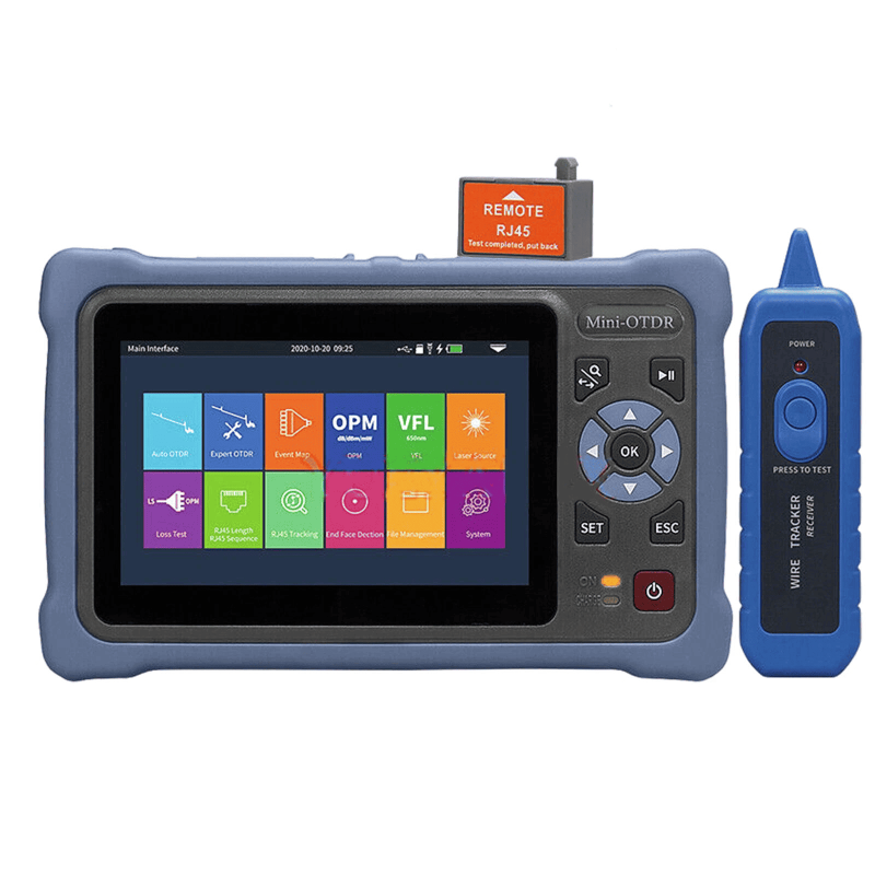
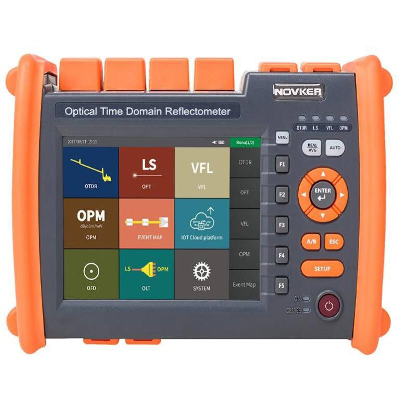
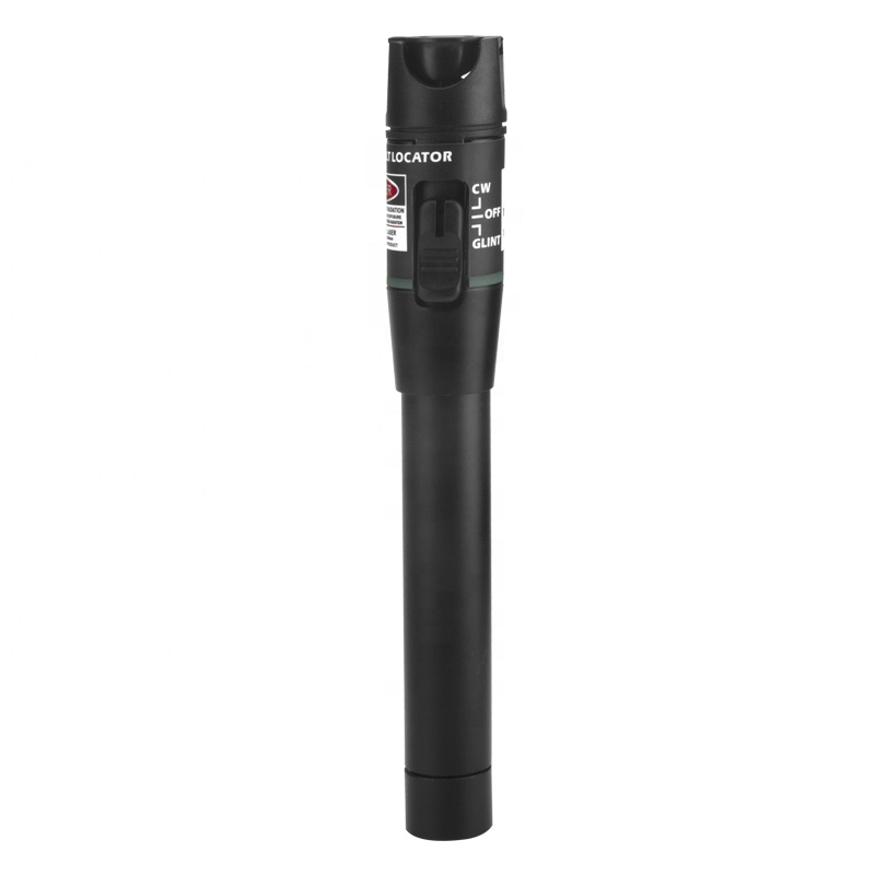
Choose the mini OTDR when the technician must locate event distance, splice loss or a break. Choose the visual fault locator for visible continuity checks and short local faults. Pair this meter with the stabilized optical light source for end-to-end insertion-loss measurement.
MOQ, Samples, Lead Time and Packing
Related Fiber Testing Tools
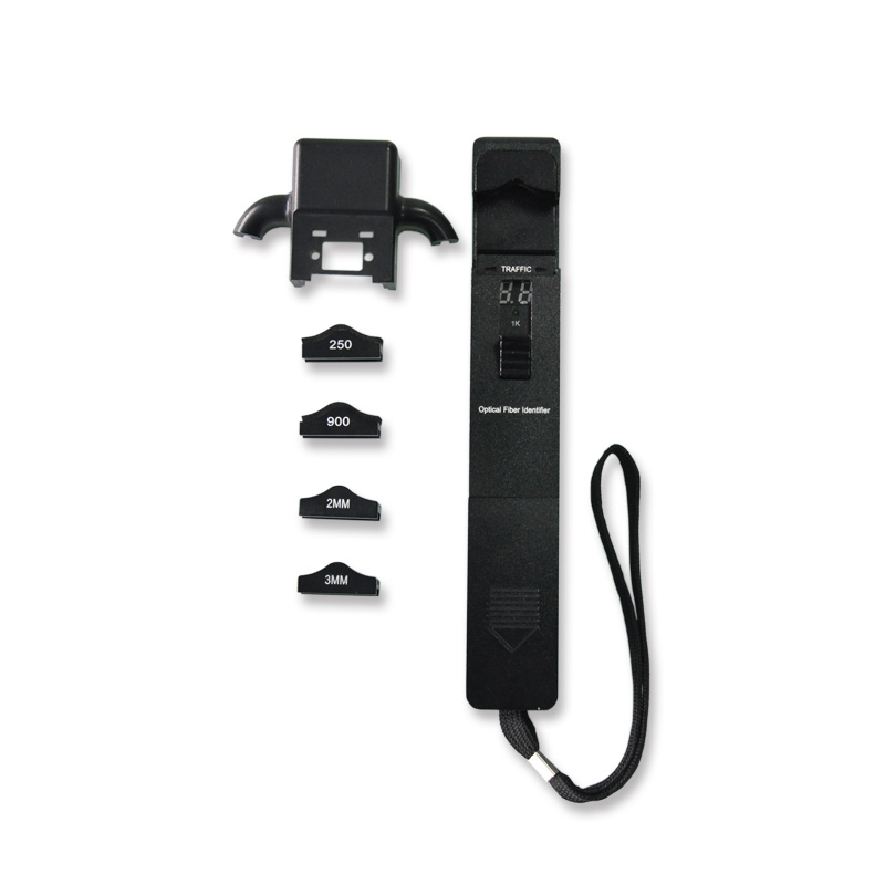
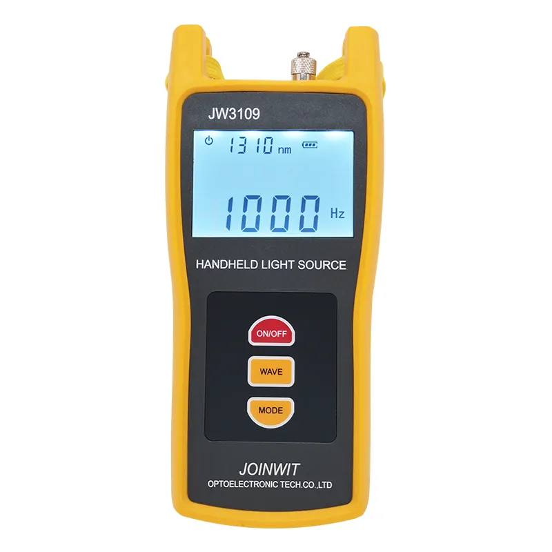
Build a complete field workflow with the 1310/1550 nm optical light source, live fiber identifier, 8-in-1 smart OTDR, cleaning tools and matched reference patch cords. LinkFiber can consolidate the kit, labels and packing for contractor or distributor orders.
How do you protect precision fiber equipment and fragile components during international transit?
Are these testing instruments durable enough for harsh outdoor fiber optic installations?
How do you guarantee the measurement accuracy of your fiber optic testing tools before shipment?
To learn more about this product, you can submit your requirements here.
 LF059 Handheld Fiber Optic Power Meter FTTH Network Cable Tester
 LF068 NK4000 Mini Pro 8-in-1 Smart OTDR
 LF063 Handheld OPM 4 in 1 Optical Power Meter With VFL
 LF-069-Professional Telecom Grade OTDR Optical Time Domain Reflectometer for Long Haul Fiber Cable Testing
 LF060 G10 Optic Power Meter Rechargeable USB with LCD Screen-High-Precision Fiber Tester
 LF-065-Telecom Grade Strong Light Fiber Optic VFL Waterproof Outdoor Cable Fault Locator
 LF-067-Mini Handheld Fiber Optic OTDR 1310/1550nm 24/22dB 60km Optical Time Domain Reflectometer FTTH Tester
 LF-071-Handheld Optical Fiber Identifier 800-1700nm Live Fiber Detector OFI Fiber Tester
 LF-072-Portable Fiber Optic Stabilized Light Source 1310/1550nm Handheld OLS FTTH Test Tool
 OTDR Fiber Extension Launch Cable Box
 LFW2 / W2S Mini Stable Optical Light Source
 LF064 Y8 Multifunction Optical Power Meter

Professional Consultation
If you are interested in our products and would like to know more details, please leave a message here, and we will get back to you as soon as possible.


