



Products
‹
›
‹
›
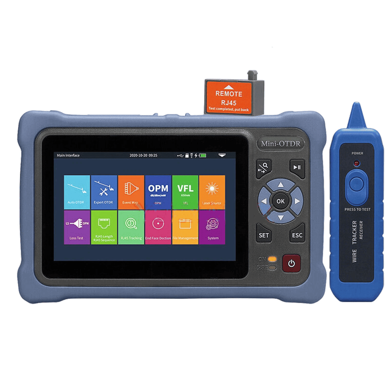
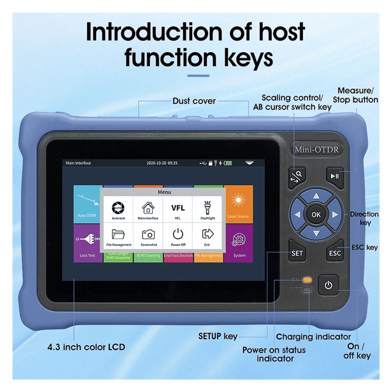
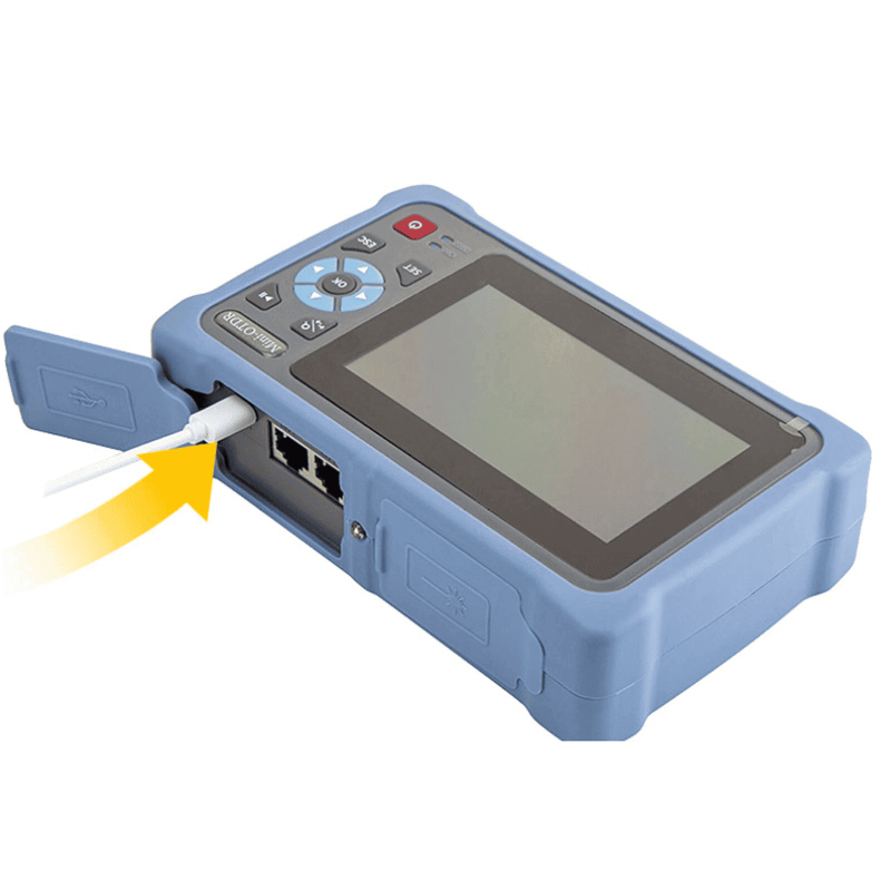
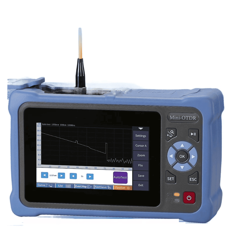
LF068 NK4000 Mini Pro 8-in-1 Smart OTDR
Share on





8-in-1 Mini OTDR for FTTH Fault Location and Field Acceptance
Mini OTDR tester combines optical time-domain reflectometry with model-dependent field functions for FTTH installation, ODN troubleshooting and maintenance. It sends a test pulse into the fibre and analyses returned light to estimate fibre length, event distance, splice or connector loss and reflection. The result is a trace and event table, not merely a red/green continuity indication.
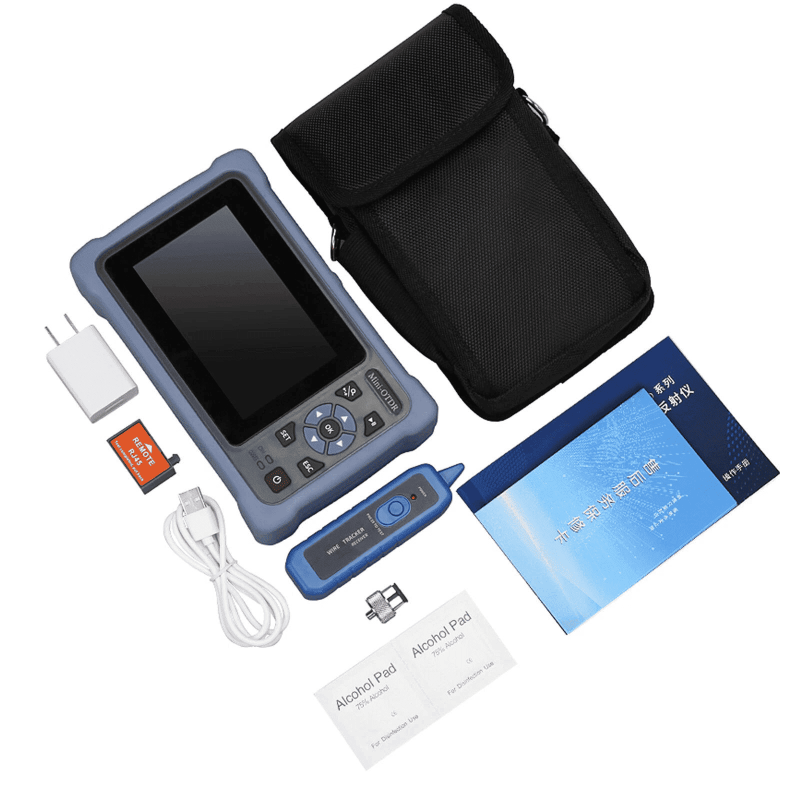
NOVKER NK4000 Mini Pro configurations are not interchangeable. Wavelength, dynamic range, event dead zone, test distance, optical port, integrated OPM/VFL/light-source functions and live-fibre capability must be confirmed on the quotation. LinkFiber can supply a matched launch cable, adapters, cleaning tools, label, manual and export kit against the approved configuration.
Where the Mini OTDR Fits in an FTTH Workflow
How to Read OTDR Specifications Before Buying
Dynamic range describes the instrument capability to see farther into a lossy link; it is not the same as the selectable distance range shown on the screen. Event dead zone affects separation of nearby reflective events, while attenuation dead zone affects how soon loss can be measured after a strong reflection. Short access links therefore require attention to dead-zone performance, not only the longest advertised distance.
Pulse width is a trade-off: a narrow pulse improves spatial resolution but provides less energy; a wide pulse reaches farther but broadens dead zones. The group index or IOR converts measured time into distance, so the project fibre value should be entered rather than copied blindly from another cable. Launch and receive fibres help characterise the first and last connectors.
Technical Specifications
Configuration control: The retained table states the current orderable concept. Request the exact NK4000 sub-model data sheet before purchase and lock wavelength, dynamic range, dead zones, distance range, connector, integrated functions, battery, memory and accessories. IEC 61746-1 concerns calibration of single-mode OTDR measurement errors and uncertainties; a generic standards claim does not replace a model-specific calibration record.
OTDR Interpretation Limits Buyers Should Understand
- Displayed distance is not guaranteed reach: usable reach depends on fibre attenuation, connector/splice loss, splitter loss, reflection, pulse width and noise floor.
- Dead zones hide nearby events: a launch cable and correct pulse width are essential when the first connector or closely spaced components must be evaluated.
- Automatic event tables require review: thresholds can miss weak events or misclassify reflections; retain the trace and test settings.
- Bidirectional loss: apparent splice loss can differ by direction because of fibre backscatter differences. High-value acceptance may require two-way analysis.
- Live-fibre testing: only use the approved filtered port and wavelength for the network; verify the operator procedure before connection.
Common Field-Failure Risks and Prevention
Pre-shipment Quality and Acceptance Plan
- Verify the exact sub-model, wavelength, dynamic range, dead-zone values, optical interface and integrated function list.
- Check OTDR trace acquisition on reference fibres with known events; review automatic event-table consistency.
- Confirm distance, loss and reflection readings against controlled references at agreed settings.
- Test OPM, VFL, light-source or network functions only when included in the ordered configuration.
- Inspect ports, battery, display, charger, language, memory/export function, serial label and full accessory list.
B2B Buyer Guide: Information Required for an Accurate Quote
- Network type and topology: point-to-point, PON/ODN, splitter ratio, typical link loss and maximum physical distance.
- Required wavelengths, dynamic range, event/attenuation dead zones, SOR export and report format.
- Whether live-fibre testing is required and the approved filtered wavelength/port for that network.
- Launch/receive cable length, fibre type, connector style and polish; include cleaning and inspection tools.
- Language, plug, battery, storage, app/software expectations, OEM label, warranty and calibration/report scope.
When to Use an OPM, VFL or Higher-Range OTDR
Use an optical power meter with a stable source for end-to-end insertion loss. Use a VFL for visible local continuity faults. Choose the telecom-grade OTDR when a larger display, higher specified dynamic range, more detailed trace control or long-route reporting is required.
MOQ, Samples, Lead Time and Packing
Related Fiber Testing Tools
Combine the mini OTDR with a matched launch cable, connector adapters, cleaning tools, live fibre identifier, reference patch cords and a calibrated OPM/OLS pair. LinkFiber can consolidate one repeatable field kit for contractor crews or distributor stock.
What is your warranty policy and after-sales support for B2B orders?
Can I test live fiber optic cables without interrupting network traffic?
To learn more about this product, you can submit your requirements here.
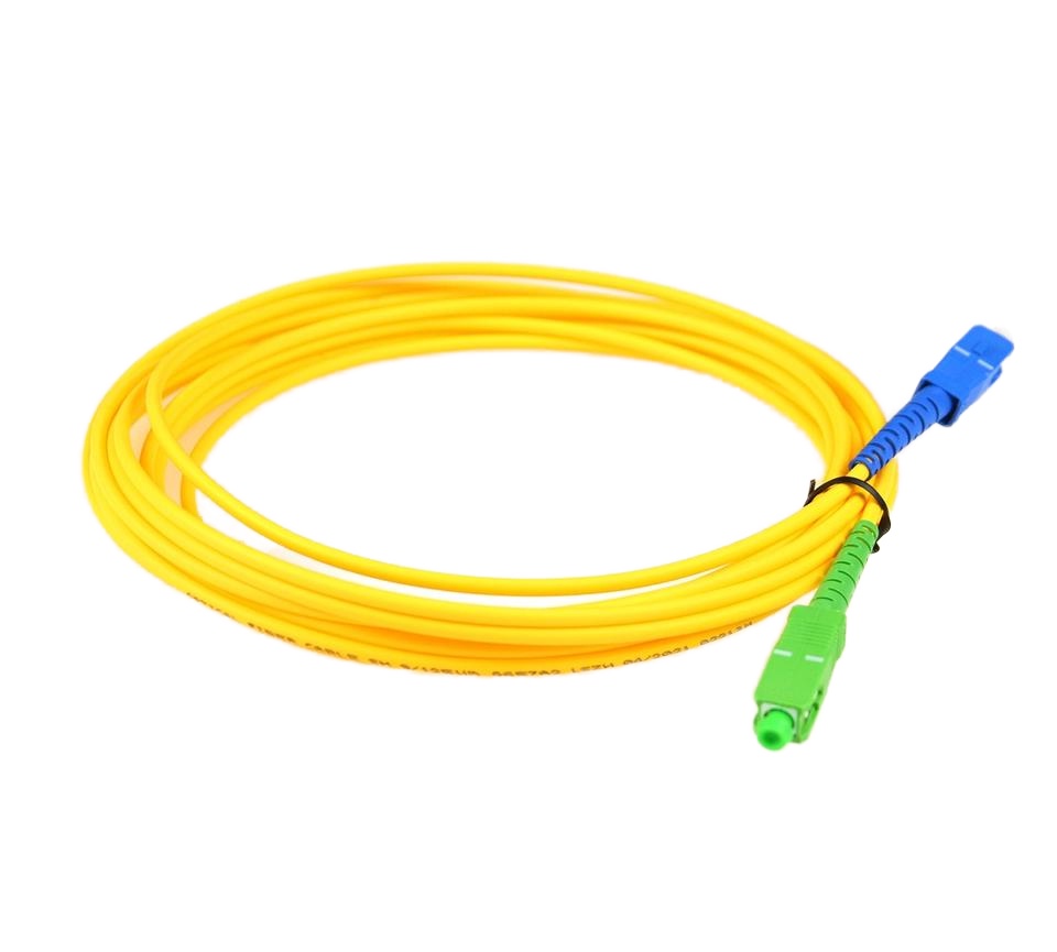
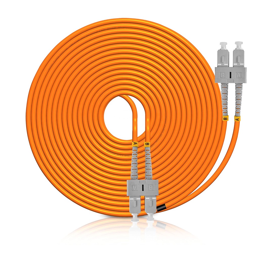
 LF005 Wholesale Optical Fiber Jumper Patch Cord Sc APC UPC 3M 2M 1M
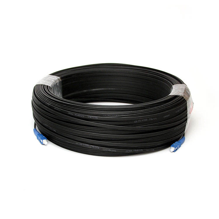
 LF001 Single Mode G.657A SC UPC to SC UPC FTTH Drop Cable Fiber Patch Cord
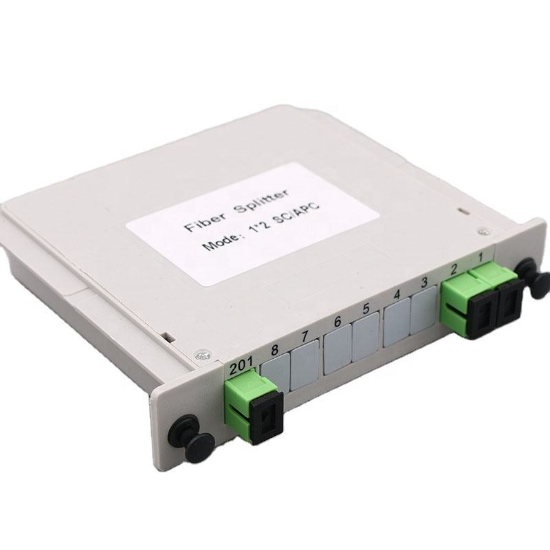
 LF012 PLC PON Fiber Optic Splitter SC/LC/FC/ST for FTTH Solutions
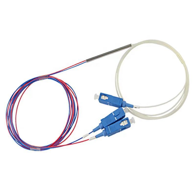
 LF016 Mini PLC Fiber Optic Splitter Blockless Series 1×2/1×4/1×8/1×16
 LF020 Splice Pigtailed PLC Splitter ABS Box Single Mode FTTH Optical Coupler
![LF028 LC SC FC fiber optic adapter flange coupler for single mode multimode links]() LF028 LC/SC/FC Fiber Optic Flange Connectors Single Mode Multimode Fiber Optic Coupler
LF028 LC/SC/FC Fiber Optic Flange Connectors Single Mode Multimode Fiber Optic Coupler LF031Fiber Optic Pigtail Single Core & 12 Core Bundle 0.9mm 1.5m G.652D Single Mode
 LF009 Multimode Fiber Patch Cords OM3 SC LC 50/125μm Low Insertion
 LF022 Custom Split Ratio Non-uniform FBT Fiber Splitter 1310/1550nm Dual Window Low Loss
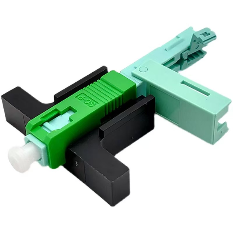
 LF025 FTTH Fiber Optic Aircraft Fast Connector
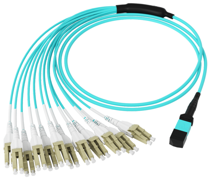
 LF104 High-Density MPO Patch Cable
 LF002 Single-mode Fiber Optic Patch Cord Simplex Duplex SC/FC/LC 2.0mm 3.0mm LSZH PVC

Professional Consultation
If you are interested in our products and would like to know more details, please leave a message here, and we will get back to you as soon as possible.


