



‹
›
‹
›
LF-069-Professional Telecom Grade OTDR Optical Time Domain Reflectometer for Long Haul Fiber Cable Testing
Share on





Telecom-Grade OTDR for Long-Haul Fiber Trace Analysis
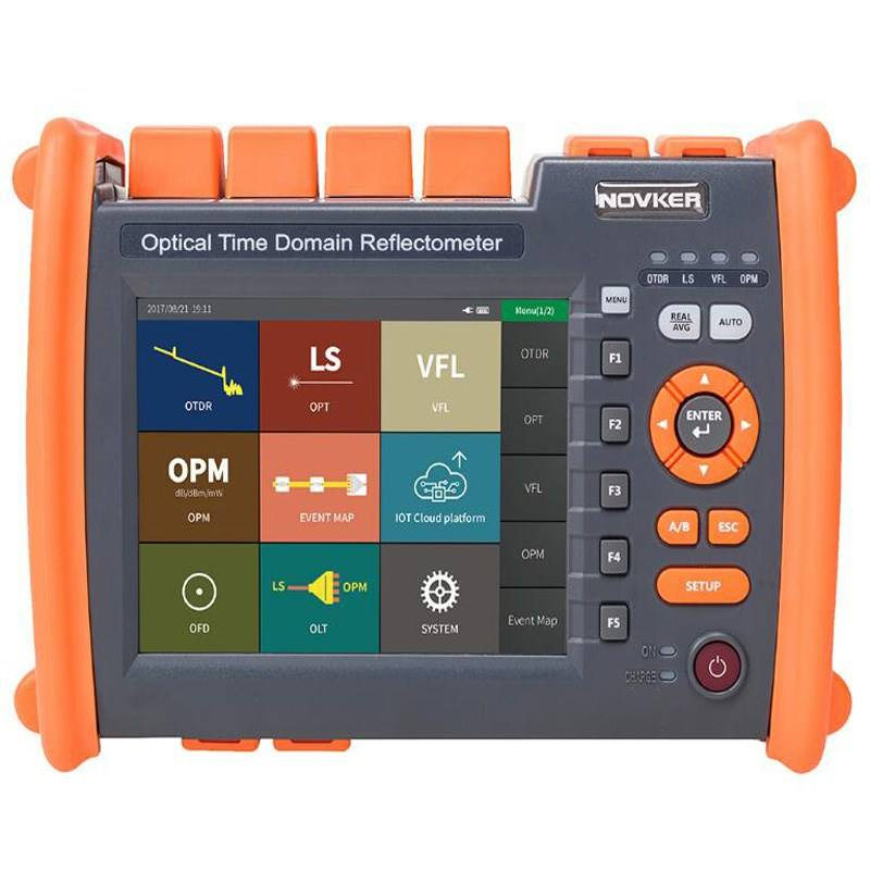
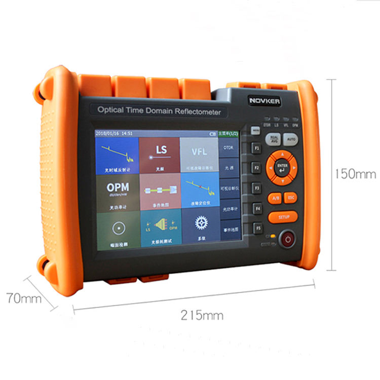
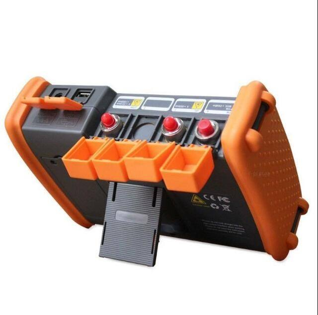
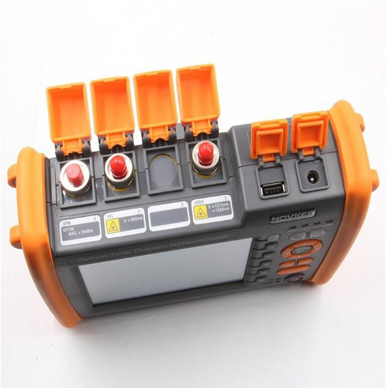
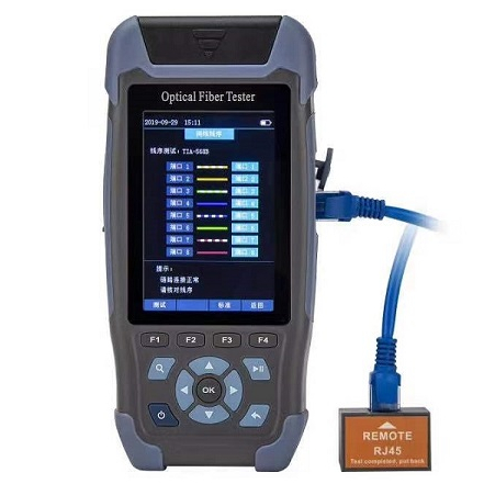
Telecom-grade OTDR is designed for single-mode route commissioning, long-distance fault location, splice/connector analysis and documented acceptance. The NK5600 series uses 1310/1550 nm testing with model-defined dynamic range, short dead zones, adjustable pulse width and native trace storage so engineers can examine where loss and reflection occur along a link.
Long-distance capability is determined by the complete link budget and test settings, not only the 120 km screen range. Fibre attenuation, splitter loss, reflections, pulse energy, averaging time and noise floor all affect the usable trace. The exact NK5600A/B/C configuration and any live-line function must be approved before quotation.
Where the NK5600 OTDR Adds Project Value
Dynamic Range, Dead Zone and Pulse Width Explained
The specified 28/26 dB dynamic range describes sensitivity under stated test conditions; it is not the same as the physical distance menu. Event dead zone determines how close two reflective events can be distinguished, while attenuation dead zone determines how soon a loss measurement can recover after reflection. Both matter on short links and patch panels even when the route itself is long.
Narrow pulses provide better spatial resolution; wide pulses improve reach but broaden dead zones. The IOR setting directly affects calculated distance. Native SOR files preserve the trace and settings for later review, while a PDF alone is convenient for handover but cannot replace the raw measurement data.
Technical Specifications
Configuration control: The detailed NK5600 table is retained. Values such as dynamic range, dead zones, drop protection, IP rating, integrated OPM/VFL/OLS functions and live-line capability must be verified for the ordered sub-model. IEC 61746-1 covers calibration of single-mode OTDR errors and uncertainties; request model/serial-specific calibration evidence where the tender requires it.
What OTDR Results Do and Do Not Prove
- One-way splice loss: backscatter differences can create apparent gainers or exaggerated loss; contractual splice acceptance may require bidirectional averaging.
- Automatic event analysis: useful for speed but dependent on thresholds; engineers should review trace shape and settings.
- Long distance selection: a 120 km range setting does not mean every 120 km link is measurable with the stated accuracy.
- Live-fibre claim: confirm filtered port, wavelength, isolation and operator procedure; standard 1310/1550 testing can interfere with service.
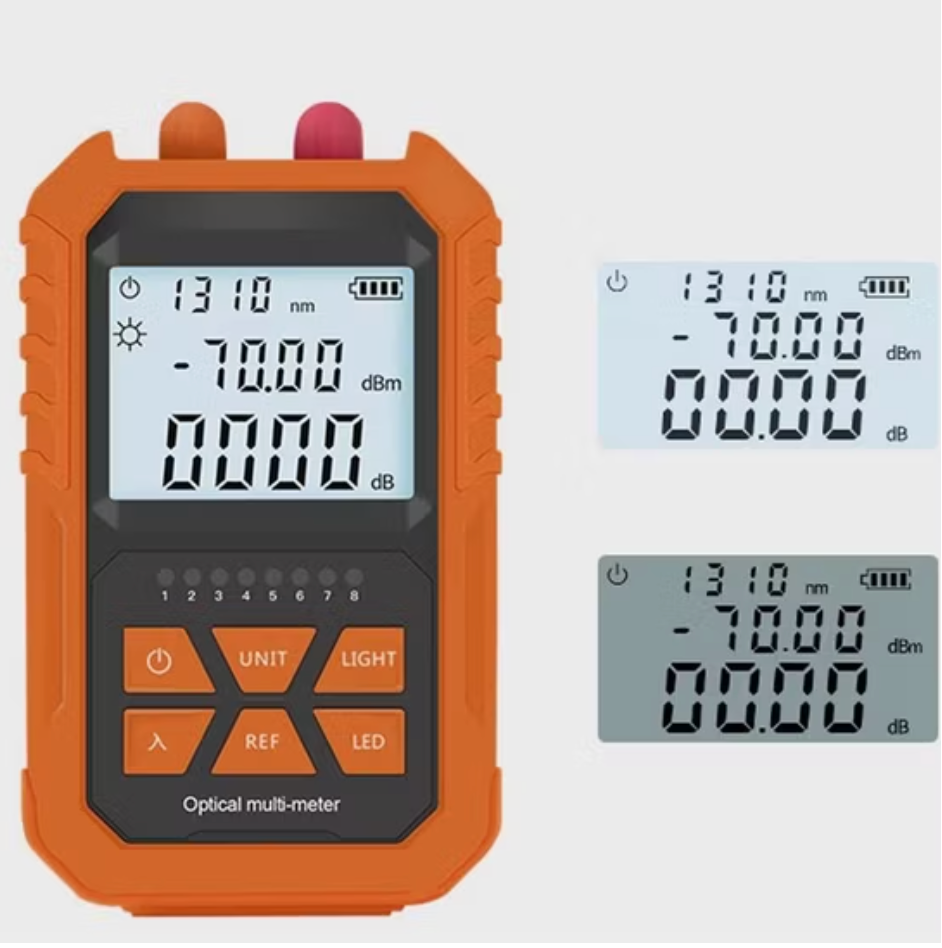
- Integrated functions: built-in OPM/VFL/OLS are field conveniences and must be verified separately if used for formal acceptance.
Common Field-Failure Risks and Prevention
Pre-shipment Quality and Acceptance Plan
- Verify sub-model, wavelength, dynamic range, dead zones, distance/pulse menus, optical interface and integrated functions.
- Test known reference events for distance, loss and reflectance consistency at agreed settings.
- Confirm SOR save/open/export, PDF generation, memory, naming, language, screen and software workflow.
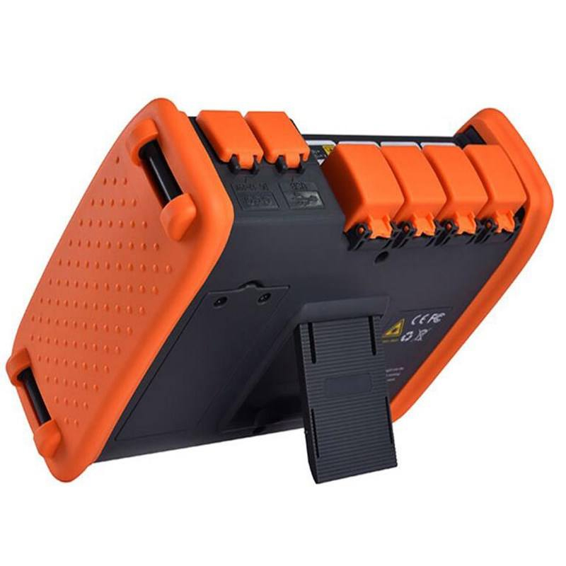
- Check battery endurance, charger, USB/TF functions, buttons/touch operation and protective housing.
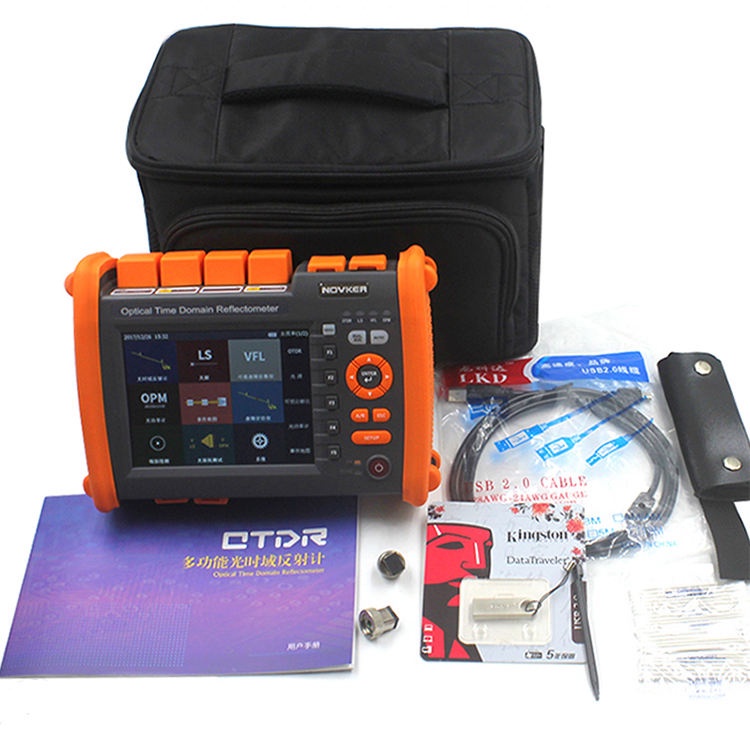
- Inspect optical port and accessories; match launch/receive fibres, adapters, cleaning kit, serial label and report.
B2B Buyer Guide: Information Required for an Accurate Quote
- Maximum link length and estimated total loss, not distance alone.
- Required wavelengths, dynamic range, event/attenuation dead zones and reporting standard.
- Splice/connector density, splitter topology and whether bidirectional or baseline testing is required.
- Live-fibre requirement with exact filtered wavelength/port and operator approval.
- Launch/receive fibres, connectors, adapters, calibration evidence, SOR/PDF workflow, language, plug and warranty.
When a Mini OTDR or OPM/OLS Pair Is Better
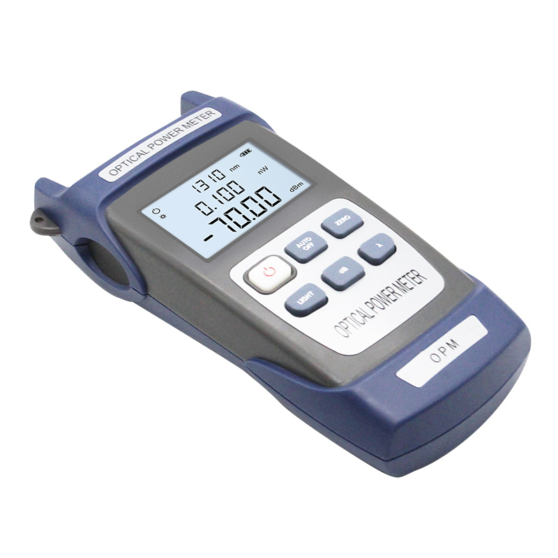
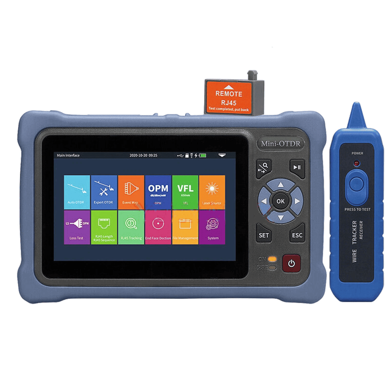
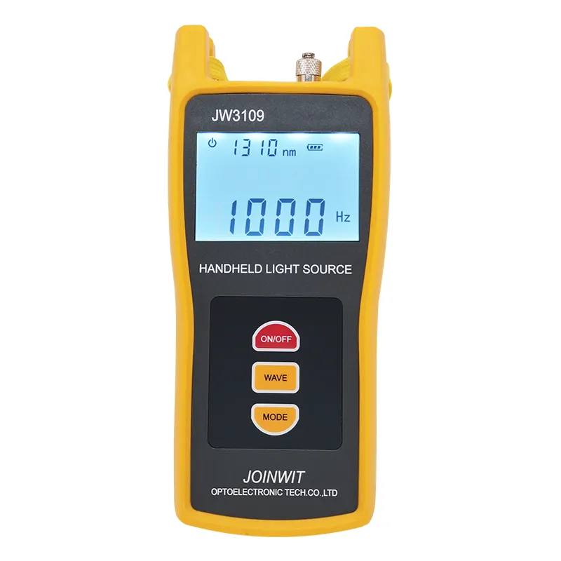
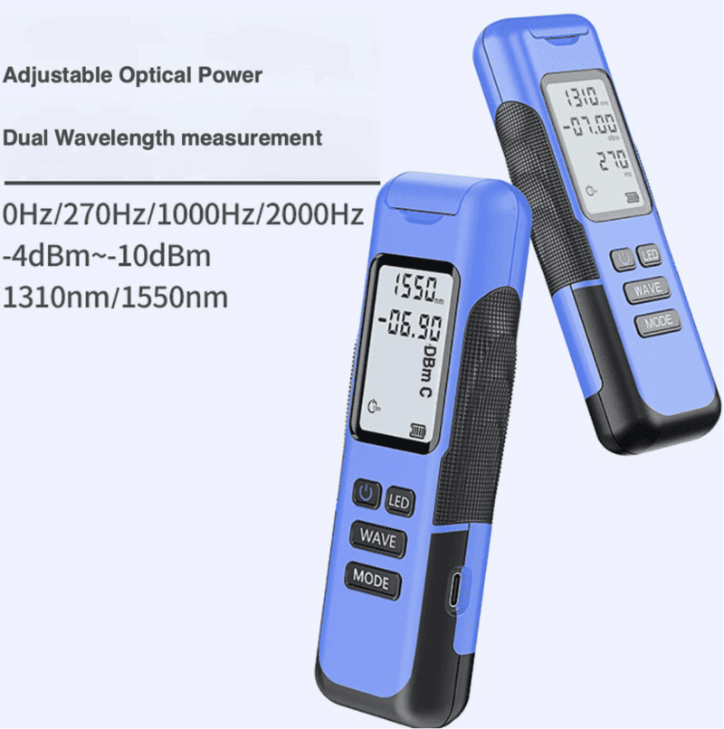
Choose the 24/22 dB mini OTDR for compact FTTH access work where its range and dead zones are sufficient. Use an OPM with a stable light source when the contractual result is end-to-end insertion loss rather than an event trace.
MOQ, Samples, Lead Time and Packing
Related Fiber Testing Tools
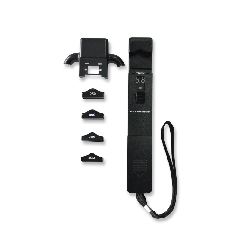
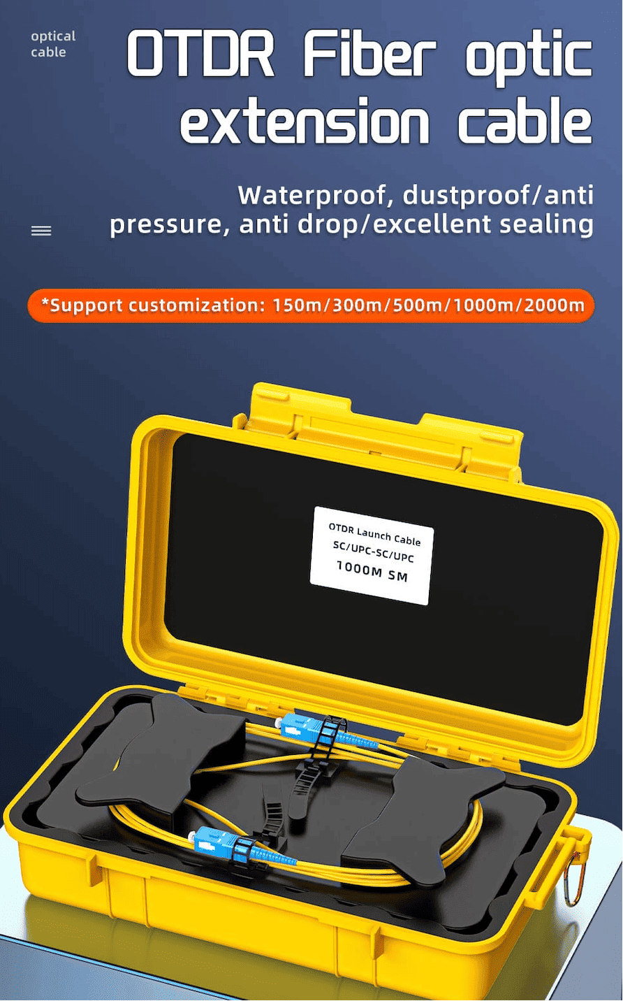
Specify launch and receive fibres, inspection/cleaning tools, reference patch cords, adapters and an optical fibre identifier as one controlled kit. LinkFiber can provide consistent labels, manuals, accessory lists and pre-shipment records for project teams.
What is a telecom grade OTDR fiber cable tester used for?
How should buyers choose OTDR dynamic range for long-haul fiber testing?
Why do OTDR dead zones matter in fiber cable testing?
Does an OTDR need a launch cable for accurate testing?
What should B2B buyers confirm before ordering telecom grade OTDRs in bulk?
To learn more about this product, you can submit your requirements here.
 LF059 Handheld Fiber Optic Power Meter FTTH Network Cable Tester
 LF068 NK4000 Mini Pro 8-in-1 Smart OTDR
 LF063 Handheld OPM 4 in 1 Optical Power Meter With VFL
 LF-069-Professional Telecom Grade OTDR Optical Time Domain Reflectometer for Long Haul Fiber Cable Testing
 LF060 G10 Optic Power Meter Rechargeable USB with LCD Screen-High-Precision Fiber Tester
 LF-065-Telecom Grade Strong Light Fiber Optic VFL Waterproof Outdoor Cable Fault Locator
 LF-067-Mini Handheld Fiber Optic OTDR 1310/1550nm 24/22dB 60km Optical Time Domain Reflectometer FTTH Tester
 LF-071-Handheld Optical Fiber Identifier 800-1700nm Live Fiber Detector OFI Fiber Tester
 LF-072-Portable Fiber Optic Stabilized Light Source 1310/1550nm Handheld OLS FTTH Test Tool
 OTDR Fiber Extension Launch Cable Box
 LFW2 / W2S Mini Stable Optical Light Source
 LF064 Y8 Multifunction Optical Power Meter

Professional Consultation
If you are interested in our products and would like to know more details, please leave a message here, and we will get back to you as soon as possible.


