



‹
›
‹
›
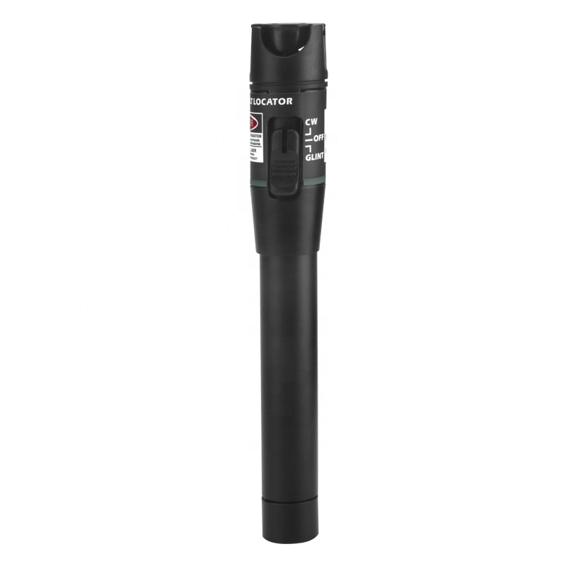
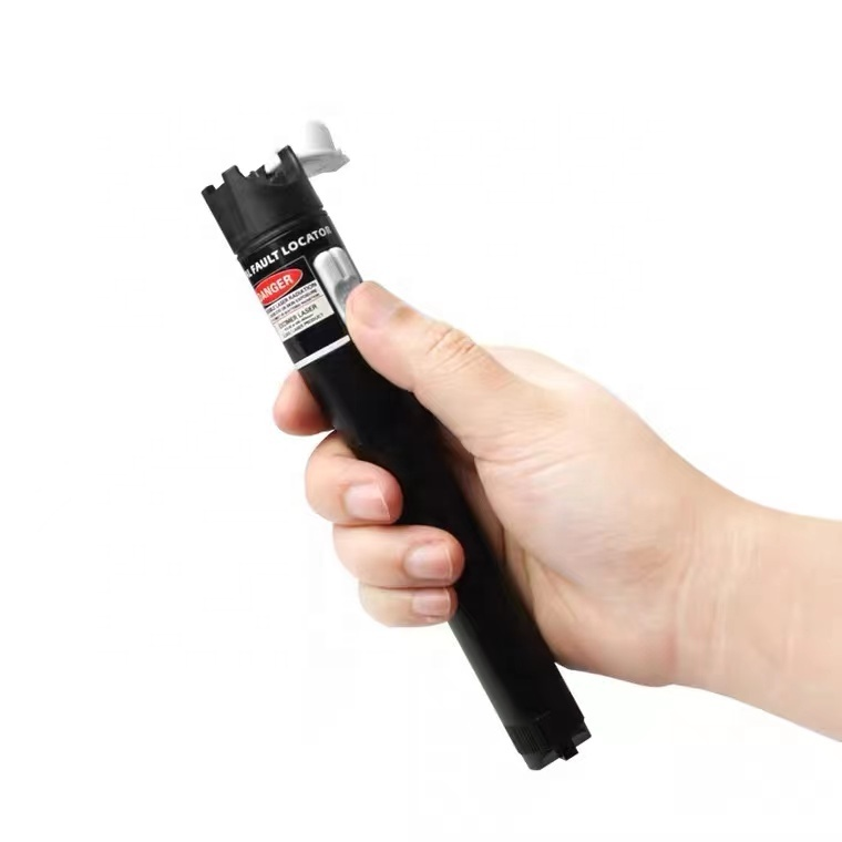
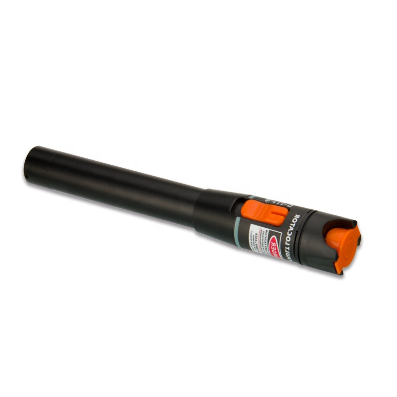
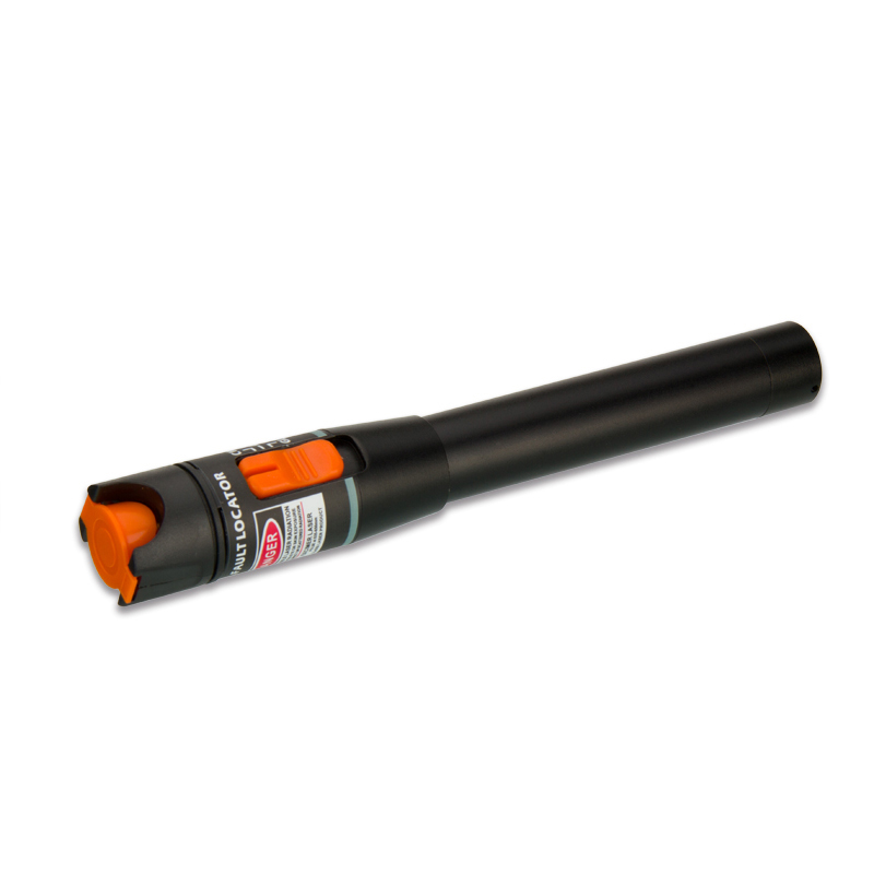
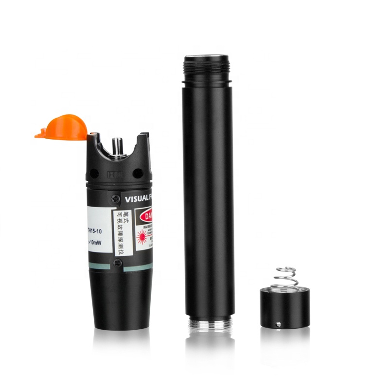
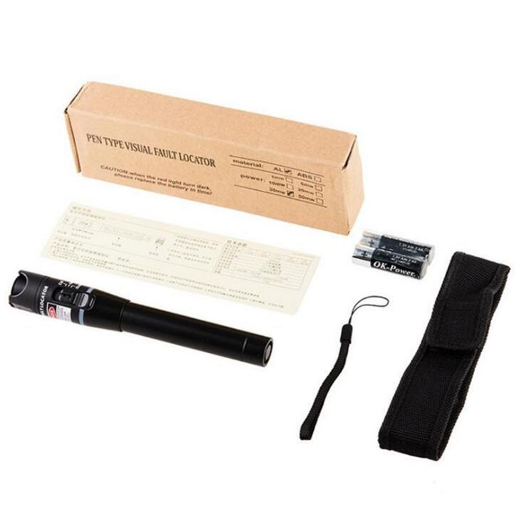
LF-065-Telecom Grade Strong Light Fiber Optic VFL Waterproof Outdoor Cable Fault Locator
Share on





650 nm Visual Fault Locator for Outdoor Fiber Continuity Checks
Visual fault locator injects visible red laser light into a fibre so technicians can check continuity, identify a fibre and find accessible sharp bends, broken points or poor connections where light escapes. This rugged VFL series offers configurable output power, CW/pulse modes and 2.5 mm interface options for FTTH, telecom maintenance and outdoor field kits.
A VFL is a qualitative locator, not a calibrated optical loss meter and not an OTDR. The visible distance depends on fibre attenuation, connector loss, bends, cable jacket, ambient light and the operator environment. Advertised kilometre reach must therefore be treated as a model/use reference rather than a contractual fault-location guarantee.
Correct VFL Use by Field Task
Output Power, Interface and Laser Safety
Higher VFL output can improve visibility under some conditions, but it also increases laser hazard and does not make opaque cable transparent. Select the lowest power that meets the controlled task. A 2.5 mm universal interface normally serves SC/FC/ST ferrules; LC requires the correct 1.25 mm adapter with alignment and cleanliness verified.
Laser classification, labelling and user precautions must match the exact output configuration. IEC 60825-1 establishes laser-product classification and requirements. Buyers should request the model-specific label, instructions and supporting documentation instead of assuming that every 1–50 mW version has the same class.
Technical Specifications
Configuration control: The original VFL Technical Specifications table is retained. Output power, claimed effective distance, interface, battery, housing, ingress protection, dimensions and laser class vary by configuration. The final quotation, sample, warning label and manual control; do not use nominal reach as the product acceptance method.
What a VFL Can and Cannot Diagnose
- Can: show continuity, identify an accessible fibre and reveal some sharp bends, open connections or breaks through visible leakage.
- Cannot: measure insertion loss, return loss, event distance or certify that a link meets its optical budget.
- Visibility varies: black PE jackets, armour, conduit, bright daylight and long routes reduce visible evidence.
- Active-network risk: verify the fibre is isolated or follow the operator-approved procedure before injection.
- Eye safety: never look into the port/fibre, point at people or use viewing optics; keep caps and labels in place.
Common Field-Failure Risks and Prevention
Pre-shipment Quality and Acceptance Plan
- Confirm exact wavelength, output power, CW/pulse behaviour, interface, adapters, battery and housing.
- Check optical output and mode switching against the approved sample or controlled reference.
- Verify laser class marking, warning label, protective cap and destination-language safety instructions.
- Inspect threads/port alignment, drop protection, sealing claim, switch lock and battery compartment.
- Match serial/model, accessories, manual, warranty and export packing before shipment.
B2B Buyer Guide: Information Required for an Accurate Quote
- Use case and environment: indoor panel, closure, outdoor route or maintenance kit.
- Required output power based on controlled task, not marketing distance alone.
- Connector/ferrule sizes, adapter requirement and fibre type.
- Battery preference, CW/pulse mode, waterproof/drop claim and operating temperature.
- Laser classification/supporting document, label language, OEM branding, quantity and packing.
When to Use an OTDR, OPM or Fiber Identifier
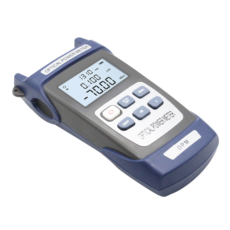
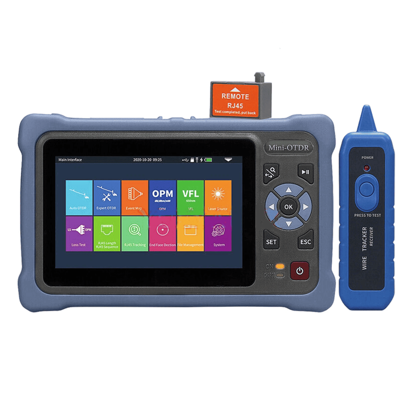
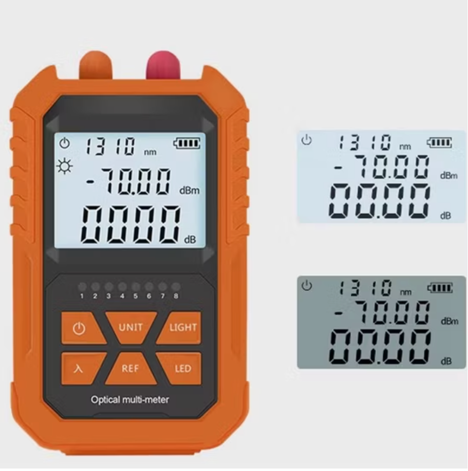
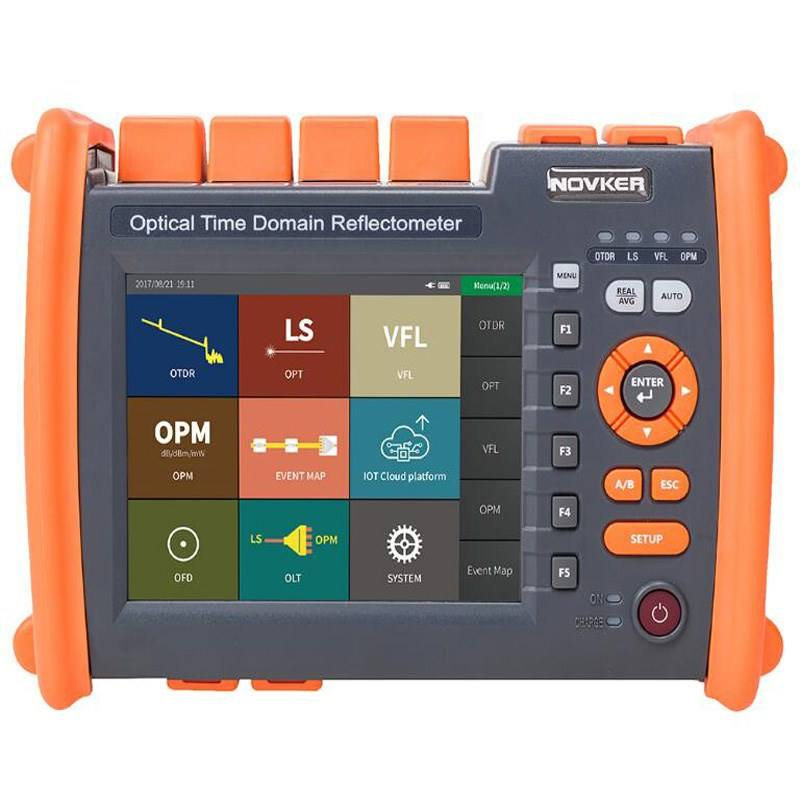
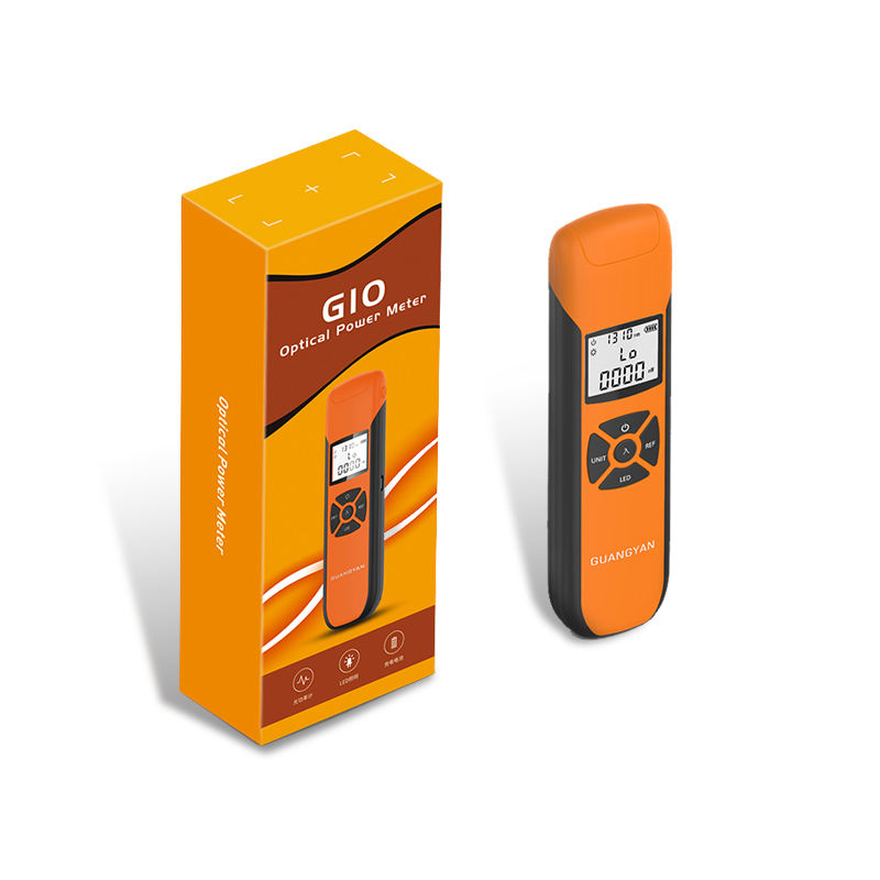
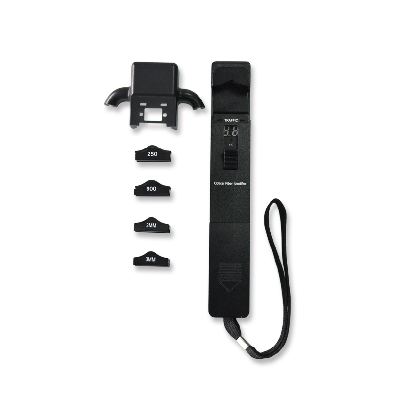
Use the mini OTDR to measure fault distance and analyse events. Use an optical power meter for power/loss values. Use the optical fibre identifier when the goal is to identify traffic direction or tone without disconnecting the fibre.
MOQ, Samples, Lead Time and Packing
Related Fiber Testing Tools
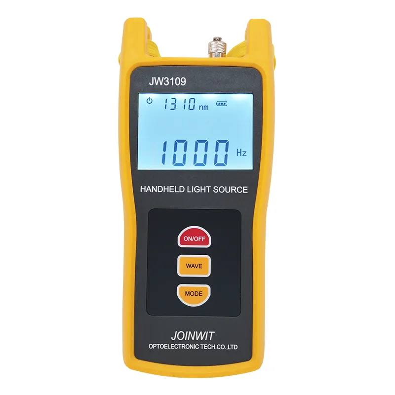
A field kit can combine the VFL with cleaning tools, adapters, reference patch cords, an OPM/OLS pair and a compact OTDR. LinkFiber can standardise output power, warning labels and accessories for multiple crews.
Product Test Video: 100mW VFL Output Power Check
Before bulk sourcing a visual fault locator, buyers should not rely only on the labelled output power or the lowest quoted price. LinkFiber tested a 100mW VFL reaching about 108-110mW, helping distributors avoid underpowered low-price products that may damage customer trust after resale or field use.
How do you protect precision fiber equipment and fragile components during international transit?
Are these testing instruments durable enough for harsh outdoor fiber optic installations?
How do you guarantee the measurement accuracy of your fiber optic testing tools before shipment?
To learn more about this product, you can submit your requirements here.
 LF059 Handheld Fiber Optic Power Meter FTTH Network Cable Tester
 LF068 NK4000 Mini Pro 8-in-1 Smart OTDR
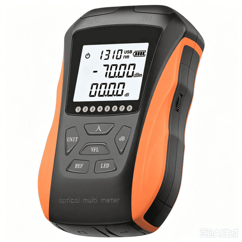
 LF063 Handheld OPM 4 in 1 Optical Power Meter With VFL
 LF-069-Professional Telecom Grade OTDR Optical Time Domain Reflectometer for Long Haul Fiber Cable Testing
 LF060 G10 Optic Power Meter Rechargeable USB with LCD Screen-High-Precision Fiber Tester
 LF-065-Telecom Grade Strong Light Fiber Optic VFL Waterproof Outdoor Cable Fault Locator
 LF-067-Mini Handheld Fiber Optic OTDR 1310/1550nm 24/22dB 60km Optical Time Domain Reflectometer FTTH Tester
 LF-071-Handheld Optical Fiber Identifier 800-1700nm Live Fiber Detector OFI Fiber Tester
 LF-072-Portable Fiber Optic Stabilized Light Source 1310/1550nm Handheld OLS FTTH Test Tool
 OTDR Fiber Extension Launch Cable Box
 LFW2 / W2S Mini Stable Optical Light Source
 LF064 Y8 Multifunction Optical Power Meter

Professional Consultation
If you are interested in our products and would like to know more details, please leave a message here, and we will get back to you as soon as possible.


