



‹
›
‹
›
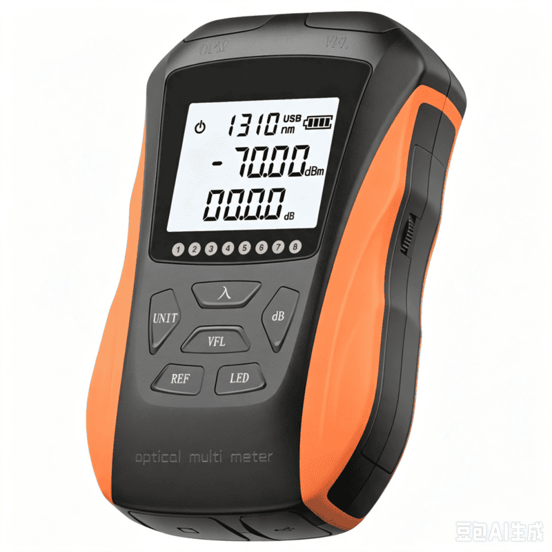
LF060 G10 Optic Power Meter Rechargeable USB with LCD Screen-High-Precision Fiber Tester
LF60A:-70~+6 dBm
LF60B1:-70~+10 dBm
LF60B2:-50~+26 dBm
Share on





G10 Rechargeable Optical Power Meter for Compact FTTH Field Kits
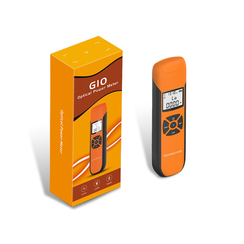
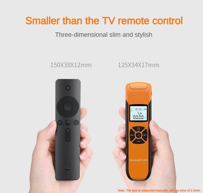
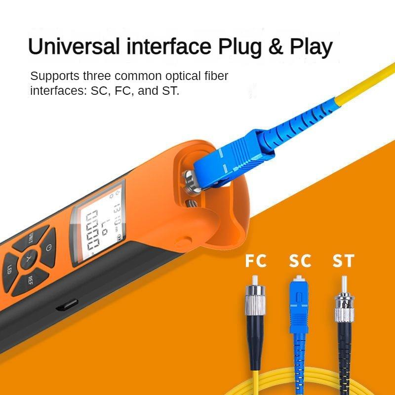
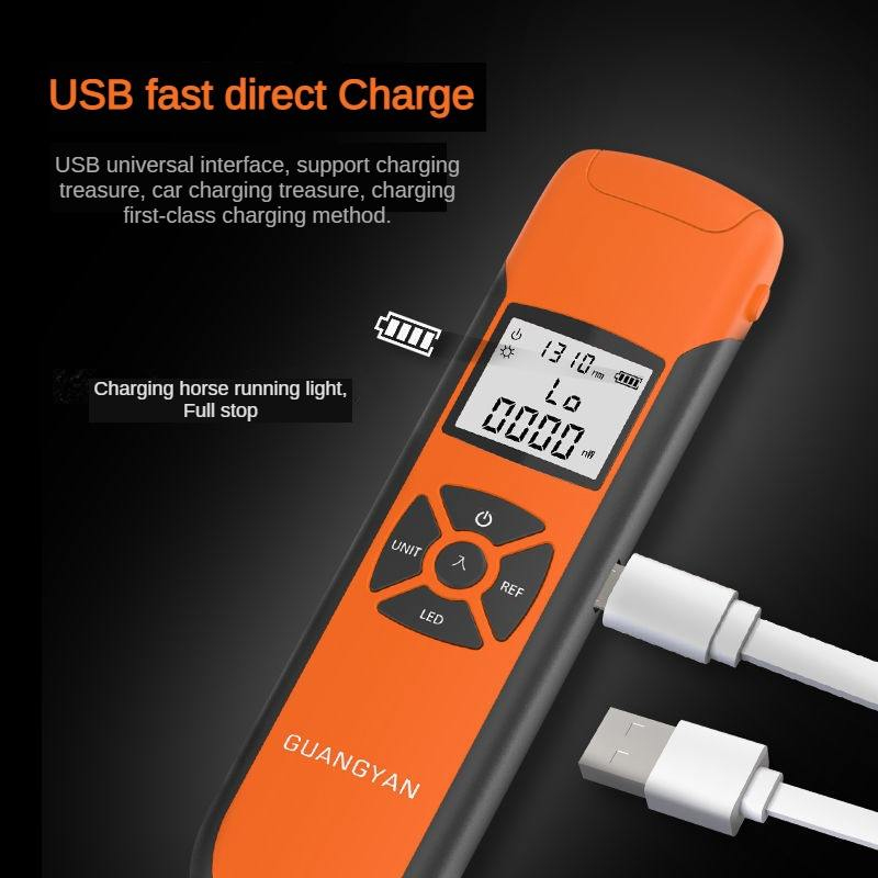
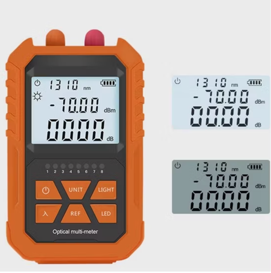
G10 optical power meter is a compact USB-rechargeable instrument for FTTH signal checks, relative loss comparison and maintenance troubleshooting. Its small format, backlit display, wavelength memory, tone recognition and data storage are intended for technicians who need frequent measurements without carrying a full-size bench instrument.
Three measuring ranges are shown for the series: low-level access-network variants and a high-power variant. The correct model must be selected from the expected signal window. A compact body does not remove the need for correct wavelength selection, clean reference cords, calibration control and a stabilized source when measuring insertion loss.
Choosing the Correct G10 Meter Variant
Compact OPM Accuracy Depends on the Full Test System
A meter reading is influenced by detector calibration, wavelength, source stability, connector cleanliness, reference-cord quality and connection repeatability. The 0.01 dB display step is useful for viewing change but does not by itself establish ±0.01 dB accuracy. Buyers should define a realistic acceptance margin based on the instrument specification and calibration uncertainty.
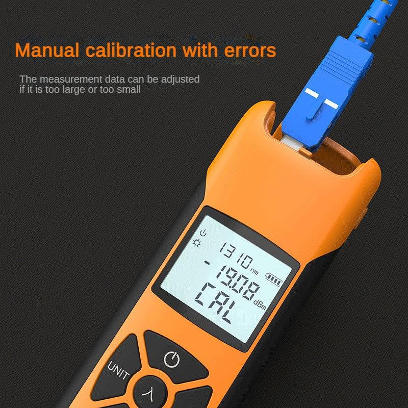
User self-calibration should be controlled. It can store an approved offset but should not be used to force agreement with an unknown source. IEC 61315 addresses calibration of fibre-optic power meters; tender compliance requires evidence for the exact ordered unit or lot, not simply the standard number in marketing text.
Technical Specifications
Configuration control: The original G10 Technical Specifications table is retained. Confirm LF60A/LF60B1/LF60B2 range, calibrated wavelengths, adapter set, battery capacity, dimensions, weight and package contents on the approved sample because current page data includes configuration-dependent values.
Measurement and Procurement Limits
- Range selection: the high-power model and high-sensitivity model serve different networks; choose from the actual signal window.
- Wavelength calibration: 800–1700 nm detector response does not mean every wavelength is calibrated; use the listed selectable wavelengths.
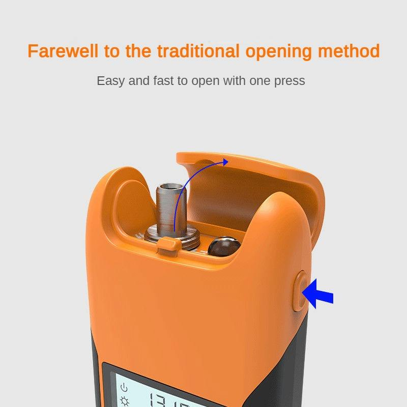
- Adapter compatibility: a 2.5 mm universal port needs the correct adapter and matching connector polish; LC normally needs an approved 1.25 mm solution.
- Rechargeable battery: confirm real duty cycle, charging input and replacement/support plan for distributor stock.
- Data storage: clarify whether 40 records are view-only or exportable and define the report workflow before purchase.
Common Field-Failure Risks and Prevention
Pre-shipment Quality and Acceptance Plan
- Verify model code, range, wavelengths, adapters, battery/USB input and included accessories.
- Compare readings at selected wavelengths and power points with a controlled reference meter.
- Check dBm/dB switching, REF function, tone recognition, data storage, backlight, flashlight and auto-off.
- Inspect port alignment, housing, display, charging connector, dust cap and serial label.
- Confirm manual language, case dimensions, packing quantity, warranty and requested calibration/inspection report.
B2B Buyer Guide: Information Required for an Accurate Quote
- Expected minimum/maximum optical power and required range variant.
- Service wavelengths, fibre type, connector/polish and required 2.5 mm or 1.25 mm adapters.
- Absolute power versus insertion-loss workflow and matching stable light source/reference cords.
- Calibration evidence, acceptance deviation, data-storage/export expectation and serial traceability.
- Battery/charger, label, manual language, case, cleaning accessories and destination requirements.
When to Select a Full-Size or Multifunction Tester
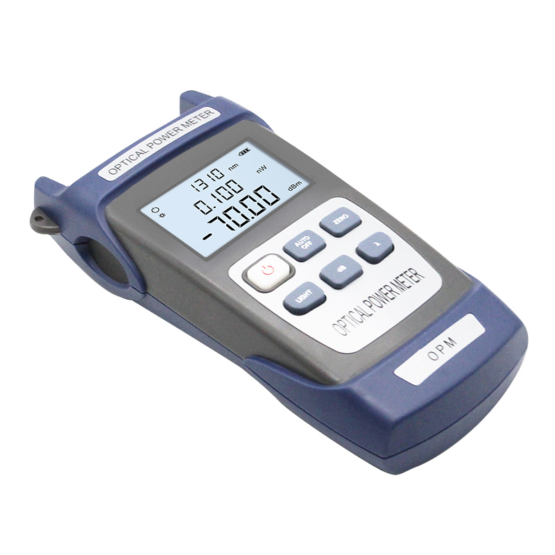
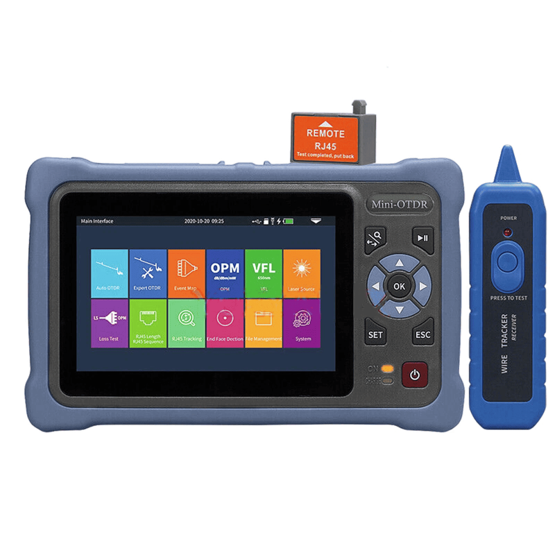
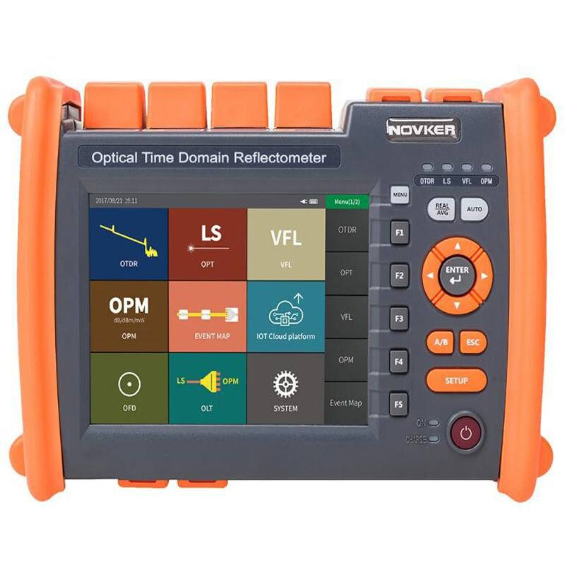
Choose the full-size handheld OPM when interchangeable accessories or AA-battery logistics are preferred. Choose the 4-in-1 OPM with VFL when visible continuity and optional combined functions reduce field-kit count. Use an OTDR for event distance and trace analysis.
MOQ, Samples, Lead Time and Packing
Related Fiber Testing Tools
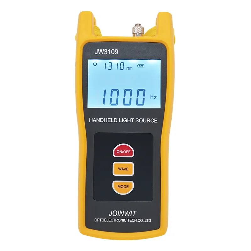
Pair the G10 OPM with the JW3109 stable light source, cleaned reference patch cords and inspection tools for repeatable loss testing.
Are your fiber optic tool kits comprehensive enough for turnkey FTTH and trunk line deployments?
How do your installation tools help technicians achieve stable, low-loss optical fiber connections?
To learn more about this product, you can submit your requirements here.
 LF059 Handheld Fiber Optic Power Meter FTTH Network Cable Tester
 LF068 NK4000 Mini Pro 8-in-1 Smart OTDR
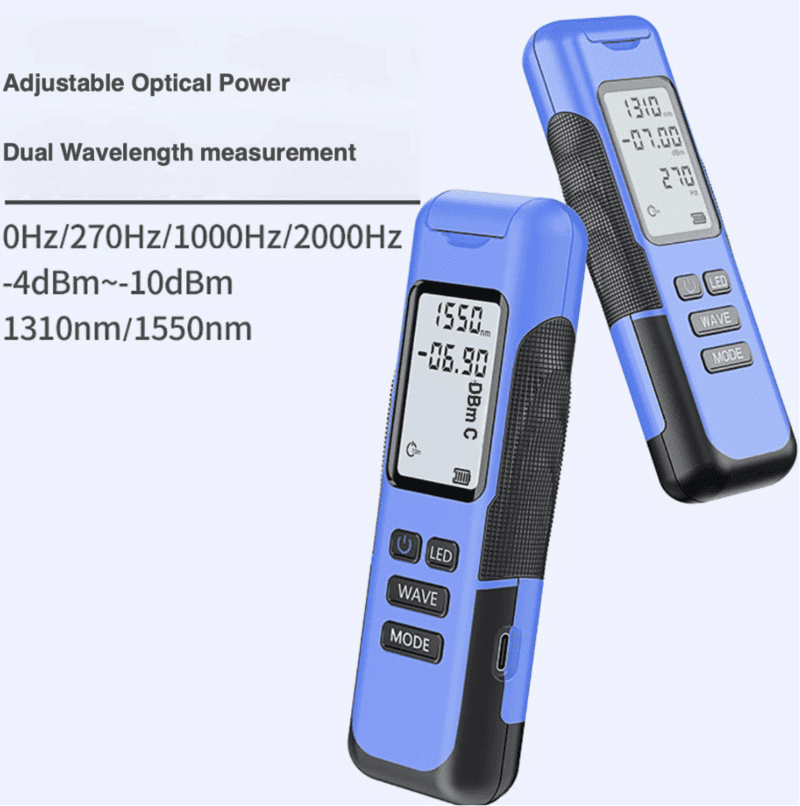
 LF063 Handheld OPM 4 in 1 Optical Power Meter With VFL
 LF-069-Professional Telecom Grade OTDR Optical Time Domain Reflectometer for Long Haul Fiber Cable Testing
 LF060 G10 Optic Power Meter Rechargeable USB with LCD Screen-High-Precision Fiber Tester
 LF-065-Telecom Grade Strong Light Fiber Optic VFL Waterproof Outdoor Cable Fault Locator
 LF-067-Mini Handheld Fiber Optic OTDR 1310/1550nm 24/22dB 60km Optical Time Domain Reflectometer FTTH Tester
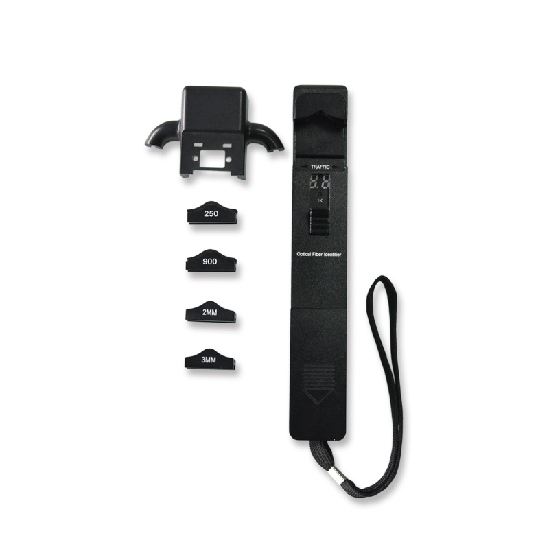
 LF-071-Handheld Optical Fiber Identifier 800-1700nm Live Fiber Detector OFI Fiber Tester
 LF-072-Portable Fiber Optic Stabilized Light Source 1310/1550nm Handheld OLS FTTH Test Tool
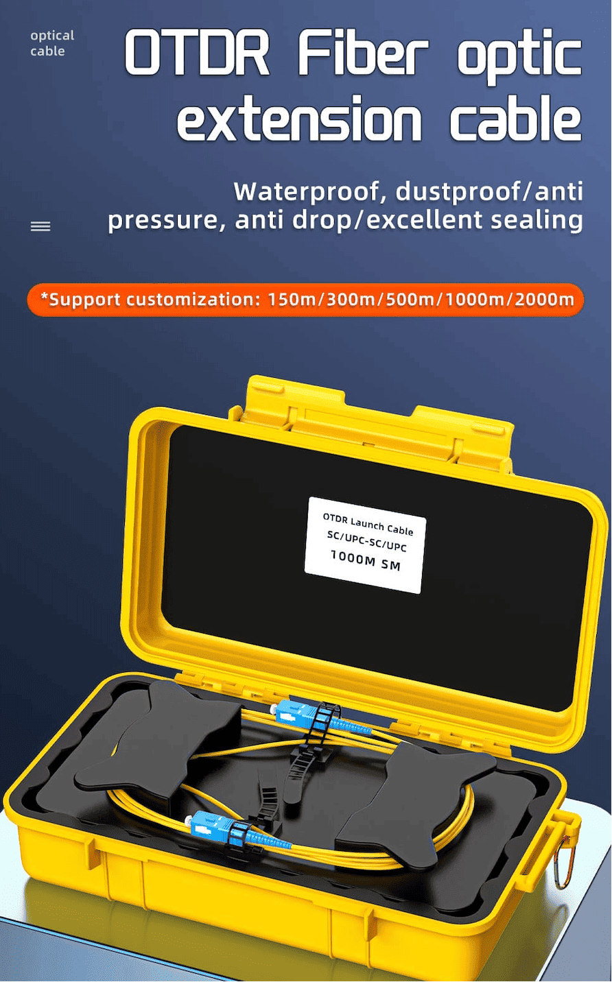
 OTDR Fiber Extension Launch Cable Box
 LFW2 / W2S Mini Stable Optical Light Source
 LF064 Y8 Multifunction Optical Power Meter

Professional Consultation
If you are interested in our products and would like to know more details, please leave a message here, and we will get back to you as soon as possible.


