



‹
›
‹
›
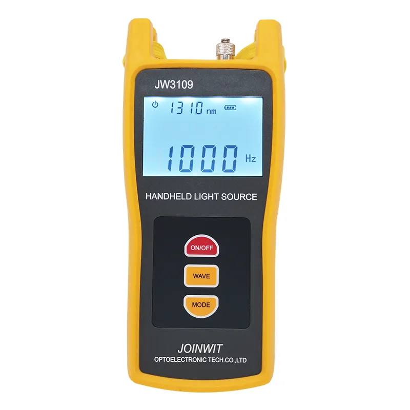
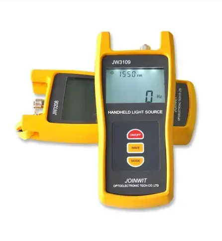
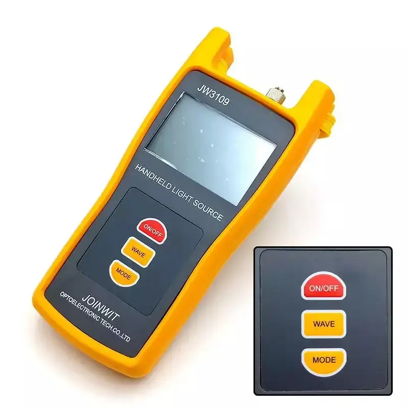
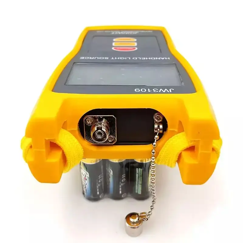
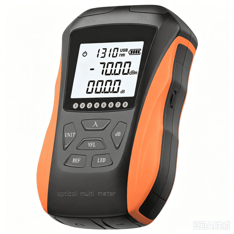
LF-072-Portable Fiber Optic Stabilized Light Source 1310/1550nm Handheld OLS FTTH Test Tool
Share on





Stabilized Optical Light Source for Single-Mode and Multimode Loss Testing
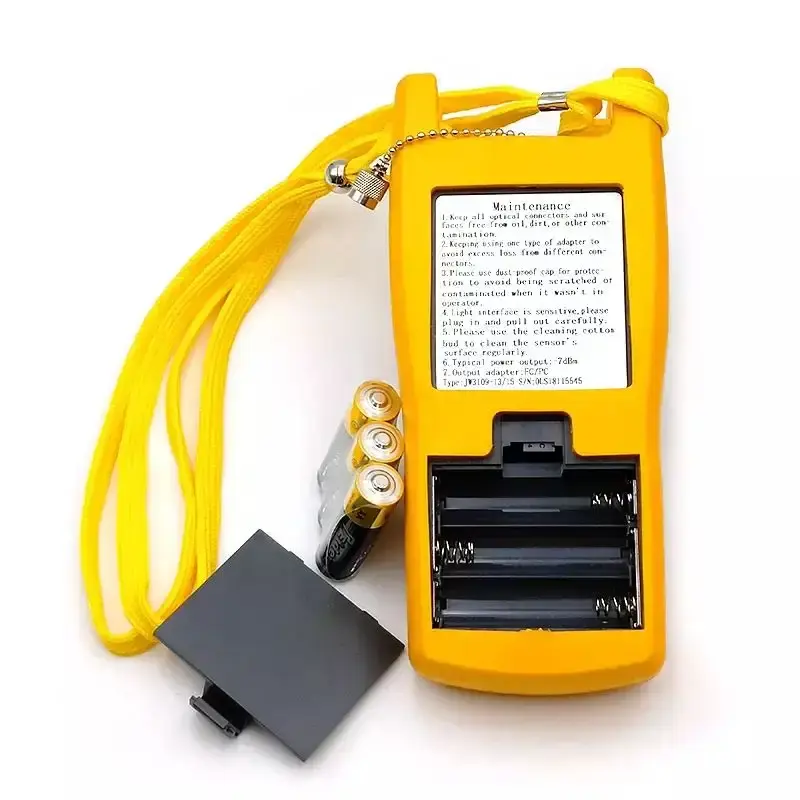
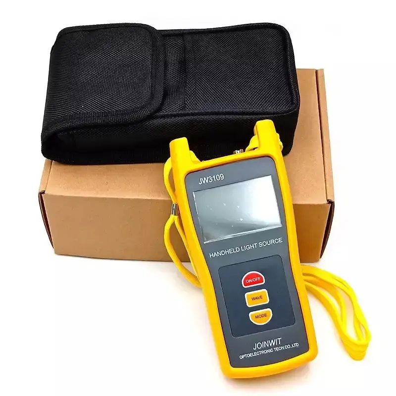
Stabilized optical light source provides a controlled output at selected fibre wavelengths so an optical power meter can measure end-to-end insertion loss. The JW3109 series can be configured with one to four outputs for single-mode or multimode work, including 1310/1550 nm and model-dependent 850/1300 nm or 650 nm functions.
An OLS is one half of a loss-test set. A defensible result requires a compatible calibrated power meter, matching wavelength, correct fibre type, stable warm-up, approved reference cords and a documented reference method. Buyers should select the JW3109A/B/C/D variant from the actual network rather than order by the phrase multi-wavelength alone.
Selecting Wavelength and Source Configuration
Reference Method and Source Stability Matter More Than One Reading
Before testing, allow the source to stabilise according to the approved method, clean and inspect all interfaces, connect the reference cord(s), then set the OPM reference. Do not disconnect the launch reference connector after the reference is established unless the method requires a new reference. Report wavelength, reference method, test-cord grade and direction with the measured dB loss.
IEC 61280-4-2 applies to attenuation and optical-return-loss measurement principles for installed single-mode cabling. IEC 61315 addresses calibration of fibre-optic power meters. The complete loss-test system—not the source alone—determines measurement uncertainty.
Technical Specifications
Configuration control: The original JW3109 Technical Specifications table is retained. Confirm exact sub-model, wavelengths, emitter type, output power, stability, modulation, connector, battery and package. Connector adapters change physical compatibility but do not automatically correct UPC/APC geometry or fibre launch conditions.
Source and Loss-Test Limits
- Wavelength pairing: the OLS and OPM must use the same calibrated wavelength.
- Single-mode versus multimode: source launch conditions are different; do not assume one generic output gives standards-aligned results for both.
- Stability: output specification depends on warm-up, time and environment; define the acceptance check.
- Modulated tones: useful for identification but formal loss testing normally uses the required stable measurement mode.
- 650 nm output: visible light is for tracing/continuity and should not be confused with 1310/1550 nm loss acceptance.
Common Field-Failure Risks and Prevention
Pre-shipment Quality and Acceptance Plan
- Verify JW3109 sub-model, wavelengths, output power, modulation frequencies, port and adapters.
- Measure short-term and agreed long-term output stability after specified warm-up.
- Check compatibility with the intended OPM and tone-recognition/fibre-identifier workflow.
- Inspect source port, display, wavelength switching, modulation, auto-off, battery and case.
- Confirm manual language, connector polish, reference cords, serial label, inspection/calibration request and packing.
B2B Buyer Guide: Information Required for an Accurate Quote
- Single-mode or multimode fibre and required test wavelengths.
- Required CW/modulated modes, output power and stability acceptance.
- Connector interface and polish, adapters, reference-cord grade and reference method.
- Matching OPM range/wavelengths, calibration evidence and project report format.
- Battery, language, carrying case, cleaning kit, OEM label, warranty, quantity and packing.
When to Add an OTDR or VFL
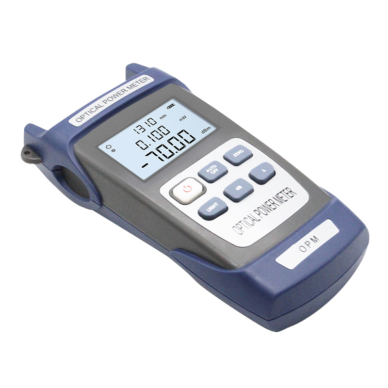
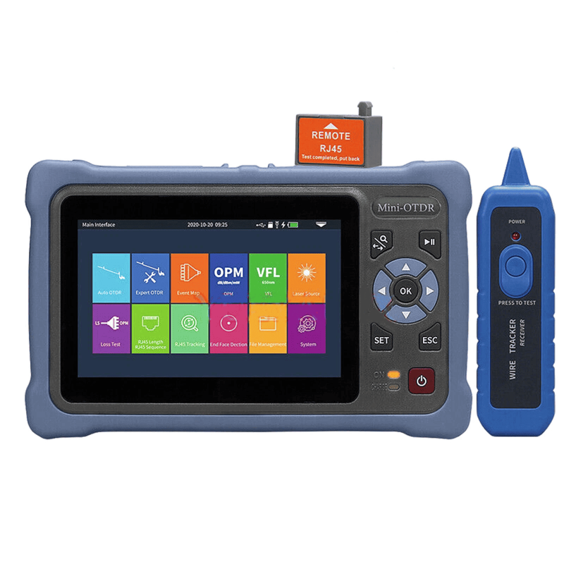
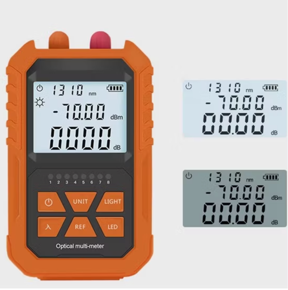
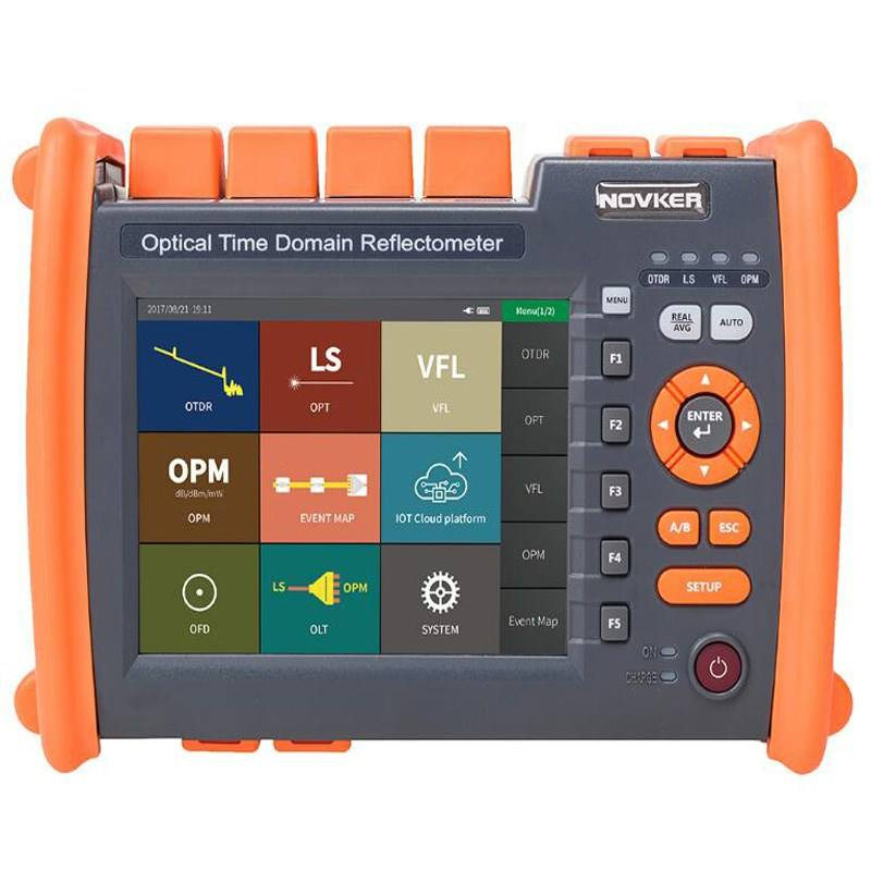
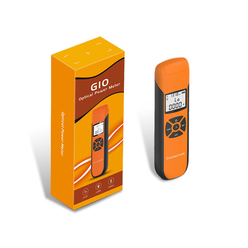
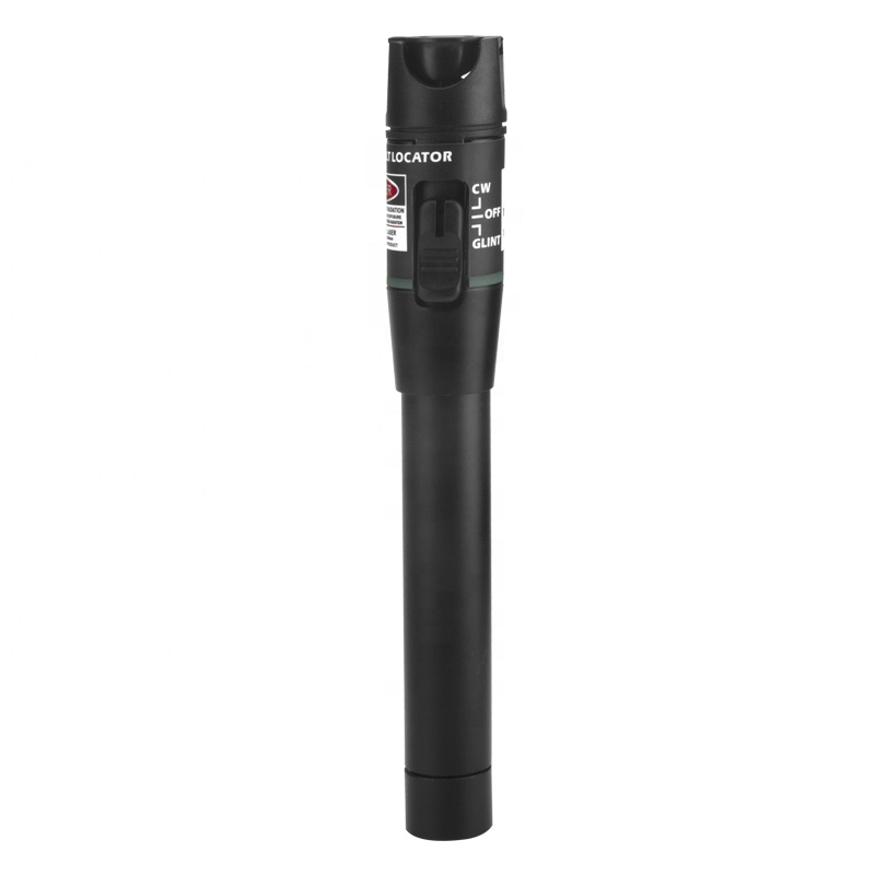
Use this source with the handheld OPM or G10 OPM for insertion-loss testing. Add a VFL for visible local continuity and an OTDR when distance/event analysis is required.
MOQ, Samples, Lead Time and Packing
Related Fiber Testing Tools
LinkFiber can supply the OLS and OPM as a matched field set with reference cords, adapters, cleaning tools, case, labels and inspection records so multiple contractor teams follow the same method.
How do you protect precision fiber equipment and fragile components during international transit?
Are these testing instruments durable enough for harsh outdoor fiber optic installations?
How do you guarantee the measurement accuracy of your fiber optic testing tools before shipment?
To learn more about this product, you can submit your requirements here.
 LF059 Handheld Fiber Optic Power Meter FTTH Network Cable Tester
 LF068 NK4000 Mini Pro 8-in-1 Smart OTDR
 LF063 Handheld OPM 4 in 1 Optical Power Meter With VFL
 LF-069-Professional Telecom Grade OTDR Optical Time Domain Reflectometer for Long Haul Fiber Cable Testing
 LF060 G10 Optic Power Meter Rechargeable USB with LCD Screen-High-Precision Fiber Tester
 LF-065-Telecom Grade Strong Light Fiber Optic VFL Waterproof Outdoor Cable Fault Locator
 LF-067-Mini Handheld Fiber Optic OTDR 1310/1550nm 24/22dB 60km Optical Time Domain Reflectometer FTTH Tester
 LF-071-Handheld Optical Fiber Identifier 800-1700nm Live Fiber Detector OFI Fiber Tester
 LF-072-Portable Fiber Optic Stabilized Light Source 1310/1550nm Handheld OLS FTTH Test Tool
 OTDR Fiber Extension Launch Cable Box
 LFW2 / W2S Mini Stable Optical Light Source
 LF064 Y8 Multifunction Optical Power Meter

Professional Consultation
If you are interested in our products and would like to know more details, please leave a message here, and we will get back to you as soon as possible.


