



‹
›
‹
›
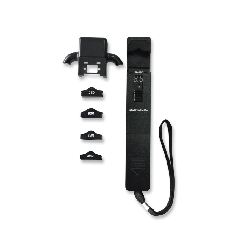
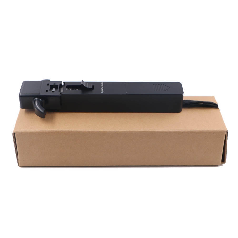
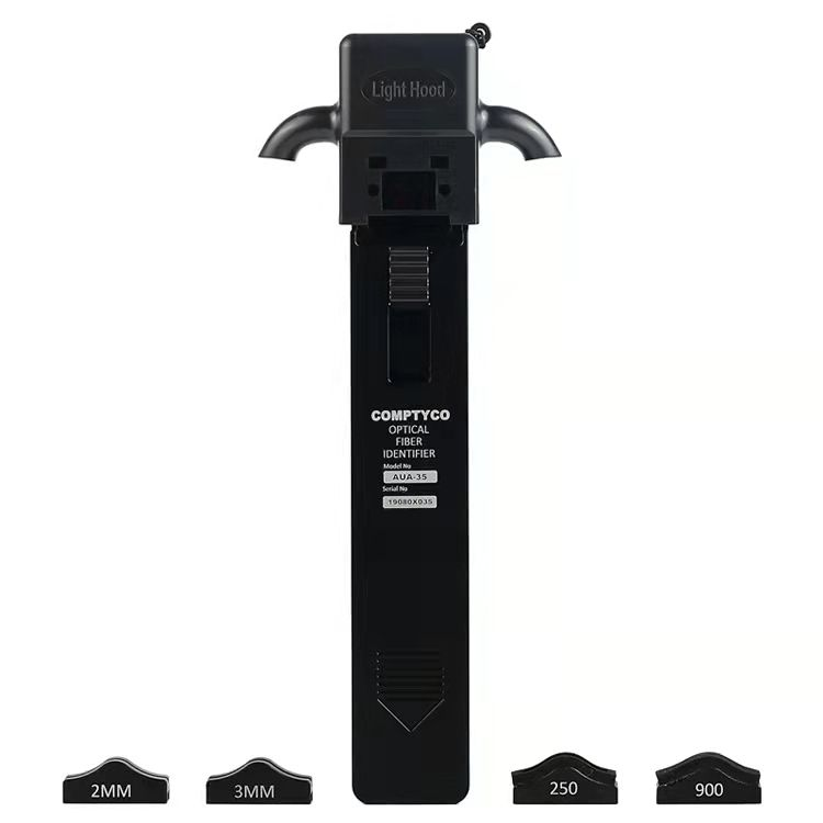
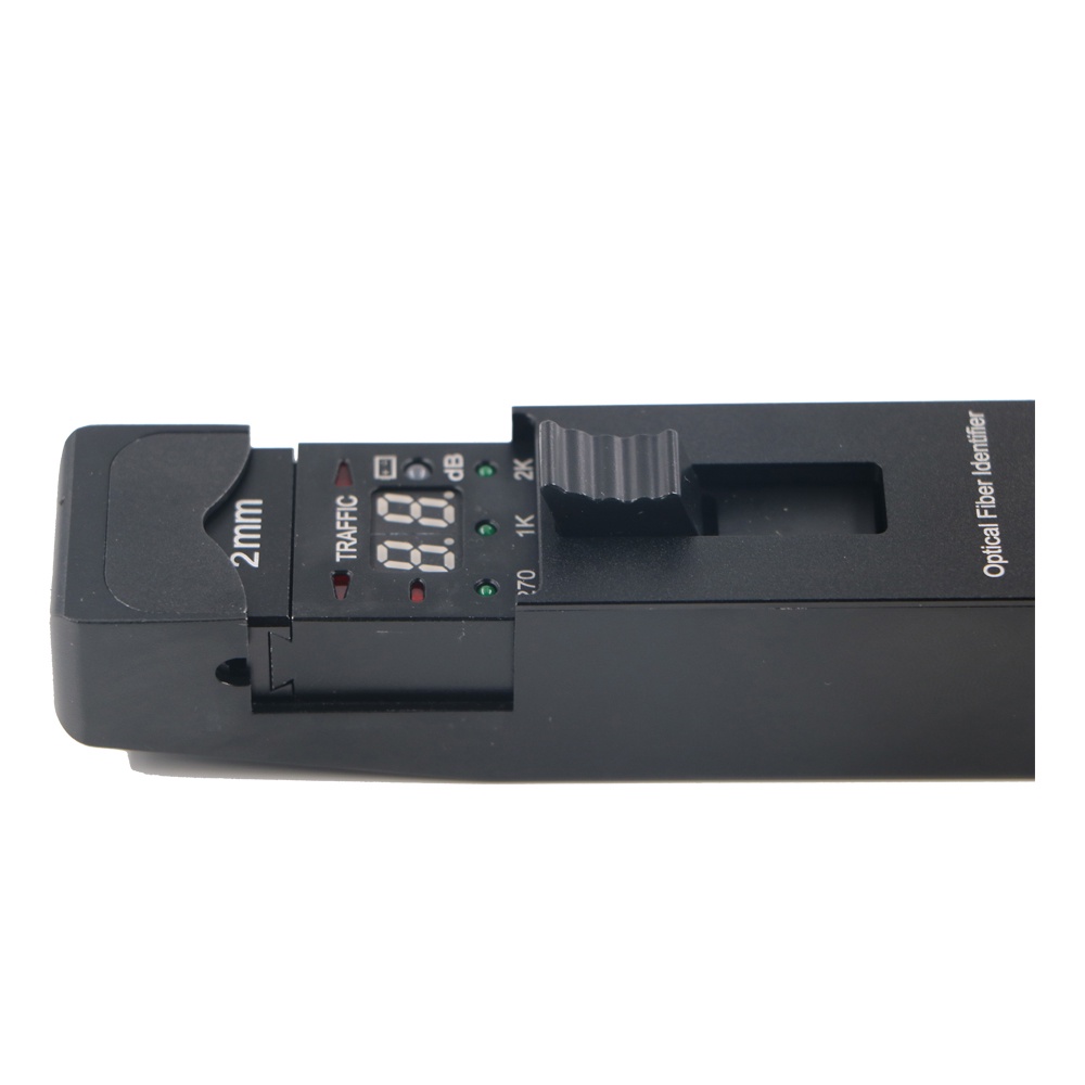
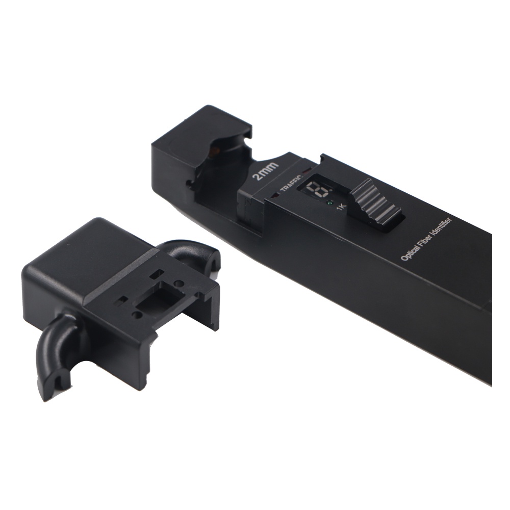
LF-071-Handheld Optical Fiber Identifier 800-1700nm Live Fiber Detector OFI Fiber Tester
Share on





Optical Fiber Identifier for Non-Destructive Live Fiber Detection
Optical fiber identifier detects light escaping from a controlled bend or clamp so technicians can identify an active fibre, determine traffic direction and recognise CW or modulated tones without disconnecting the link. It is intended for telecom maintenance, FTTH/FTTx work, patch-field management and fault isolation where cutting or unplugging the wrong fibre could interrupt service.
An identifier provides relative signal and direction information, not a calibrated end-to-end power or loss result. Detection performance depends on wavelength, fibre coating/cable diameter, clamp insert, signal level and bend-insensitive fibre design. The approved insert and operating method must match 250 μm, 900 μm, 2.0/3.0 mm or ribbon construction before bulk purchase.
Correct Use of an Optical Fiber Identifier
Macrobend Detection, Clamp Choice and G.657 Fiber
The identifier creates or uses a controlled fibre bend so a small amount of light reaches its detectors. Too little coupling gives no indication; excessive bending can add temporary loss or stress the fibre. Bend-insensitive G.657 fibre is designed to reduce macrobending loss, so identification sensitivity can differ from conventional G.652 fibre and should be verified on a project sample.
Adapter heads must support the actual construction without crushing it. Bare 250 μm fibre, buffered 900 μm fibre, round 2.0/3.0 mm cable and ribbon fibre cannot be treated as one clamp geometry. Buyers should approve the inserts, positioning method and maximum introduced loss for the exact fibre/cable.
Technical Specifications
Configuration control: The original Technical Specifications table is retained. Sensitivity, insertion-loss figures, supported fibre constructions, detector, tone recognition and accessories must be confirmed on the approved sample. A generic 800–1700 nm operating range does not mean equal sensitivity on every wavelength and cable structure.
Identification Limits Buyers Should Understand
- Relative, not absolute: LED high/medium/low does not replace a calibrated dBm measurement.
- Weak signals: fibres below sensitivity may appear dark; verify network conditions before concluding no traffic.
- G.657 and thick jackets: reduced bend leakage or mechanical shielding can reduce detection response.
- Temporary insertion loss: clamp-induced bending can affect a live service; use the correct insert and method.
- Ribbon claims: confirm whether the device identifies an individual fibre or only detects aggregate light in the ribbon.
Common Field-Failure Risks and Prevention
Pre-shipment Quality and Acceptance Plan
- Verify wavelength response, sensitivity, direction indication and tone recognition on controlled fibres.
- Test every ordered clamp insert on the stated 250/900 μm, 2.0/3.0 mm or ribbon construction.
- Measure temporary introduced loss where required by the operator procedure.
- Check audible/LED indication, battery, low-power warning, housing, clamp action and accessories.
- Confirm model/serial label, manual method, fibre compatibility statement, case and packing.
B2B Buyer Guide: Information Required for an Accurate Quote
- Fibre type and category, coating/buffer/cable diameter and whether ribbon fibre is involved.
- Typical live signal level, wavelengths and required CW/270 Hz/1 kHz/2 kHz tone recognition.
- Need for traffic direction, relative power indication and maximum acceptable temporary loss.
- Clamp inserts, battery, audible prompt, language, training/SOP and replacement accessory requirement.
- Sample validation on project cable, warranty, OEM label, inspection report and quantity.
When to Use an OPM, VFL or OTDR Instead
Use an OPM for numerical optical power, a VFL for visible continuity on a known dark fibre, and an OTDR for event distance and trace analysis.
MOQ, Samples, Lead Time and Packing
Related Fiber Testing Tools
For safe maintenance, combine the identifier with a compatible modulated light source, OPM, cleaning tools, patch cords and documented technician SOP. LinkFiber can provide a sample kit for validation before multi-crew rollout.
How do you protect precision fiber equipment and fragile components during international transit?
Are these testing instruments durable enough for harsh outdoor fiber optic installations?
How do you guarantee the measurement accuracy of your fiber optic testing tools before shipment?
To learn more about this product, you can submit your requirements here.
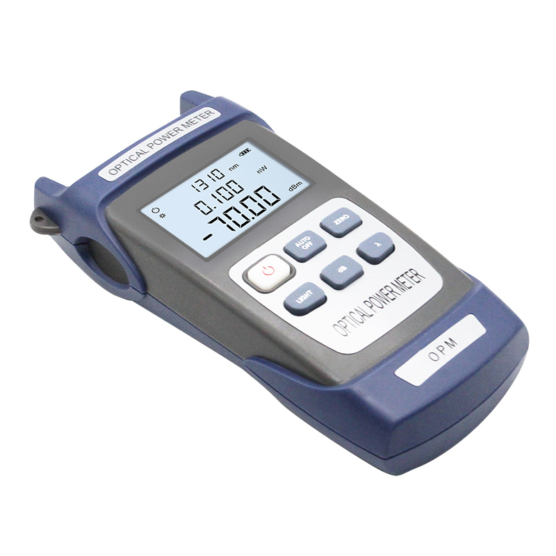
 LF059 Handheld Fiber Optic Power Meter FTTH Network Cable Tester
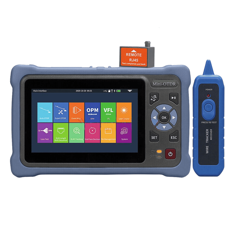
 LF068 NK4000 Mini Pro 8-in-1 Smart OTDR
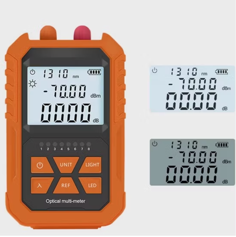
 LF063 Handheld OPM 4 in 1 Optical Power Meter With VFL
 LF-069-Professional Telecom Grade OTDR Optical Time Domain Reflectometer for Long Haul Fiber Cable Testing
 LF060 G10 Optic Power Meter Rechargeable USB with LCD Screen-High-Precision Fiber Tester
 LF-065-Telecom Grade Strong Light Fiber Optic VFL Waterproof Outdoor Cable Fault Locator
 LF-067-Mini Handheld Fiber Optic OTDR 1310/1550nm 24/22dB 60km Optical Time Domain Reflectometer FTTH Tester
 LF-071-Handheld Optical Fiber Identifier 800-1700nm Live Fiber Detector OFI Fiber Tester
 LF-072-Portable Fiber Optic Stabilized Light Source 1310/1550nm Handheld OLS FTTH Test Tool
 OTDR Fiber Extension Launch Cable Box
 LFW2 / W2S Mini Stable Optical Light Source
 LF064 Y8 Multifunction Optical Power Meter

Professional Consultation
If you are interested in our products and would like to know more details, please leave a message here, and we will get back to you as soon as possible.


