



‹
›
‹
›
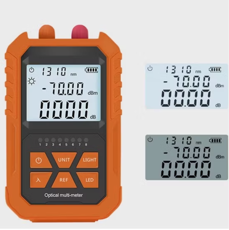
LF063 Handheld OPM 4 in 1 Optical Power Meter With VFL
Dry Battery Models:
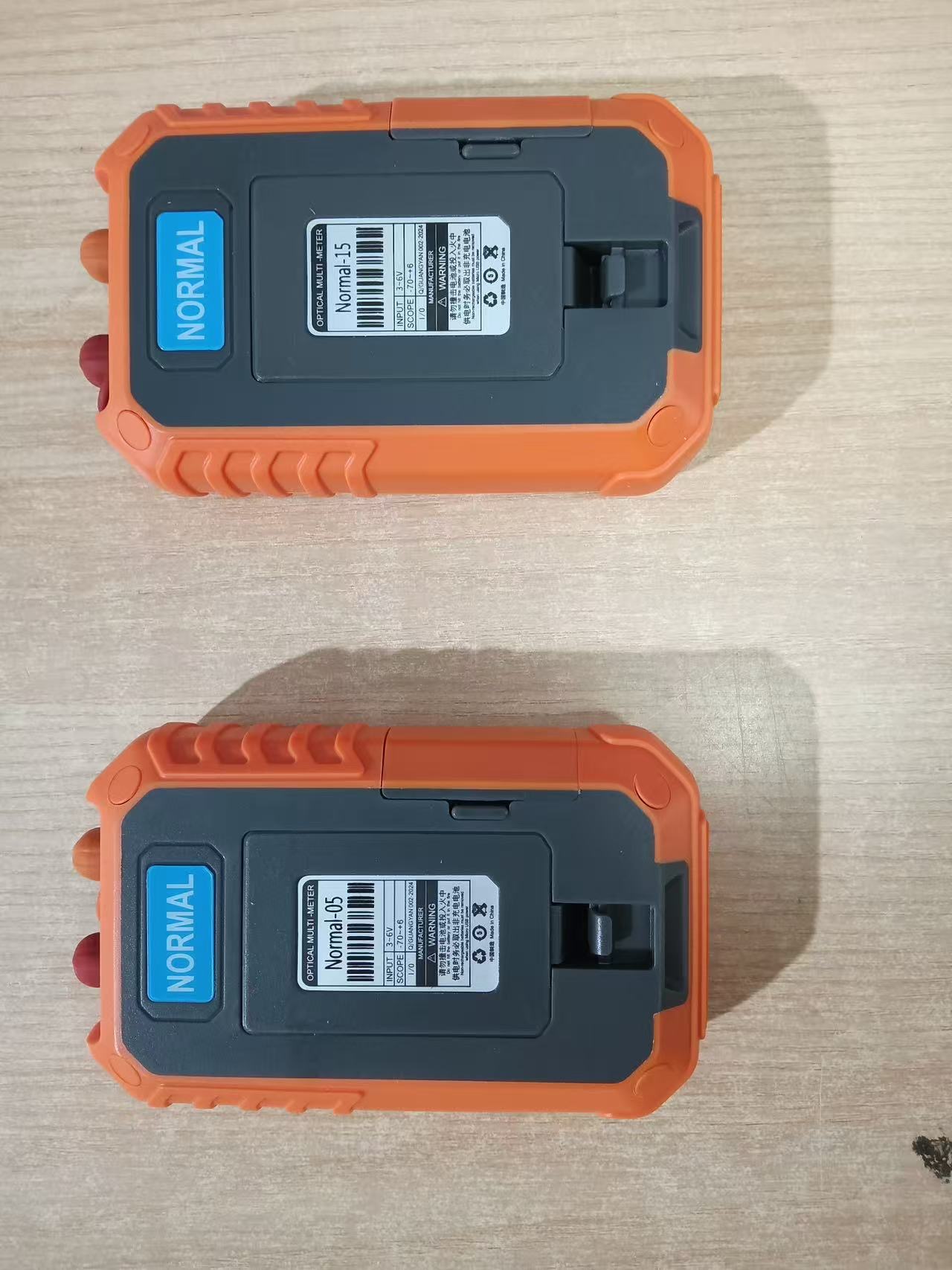
5km, -70 ~ +6 dBm;
5km, -50 ~ +26 dBm
Rechargeable Lithium Battery Models:
5km/15km/20km/30km, -70 ~ +6 dBm;
5km/15km, -70 ~ +10 dBm
5km/15km/20km/30km, -50 ~ +26 dBm
Share on





4-in-1 Optical Power Meter and VFL for FTTH Field Testing
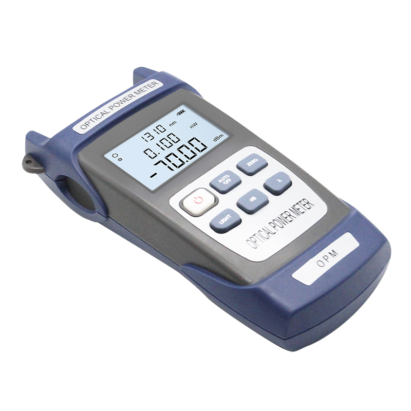
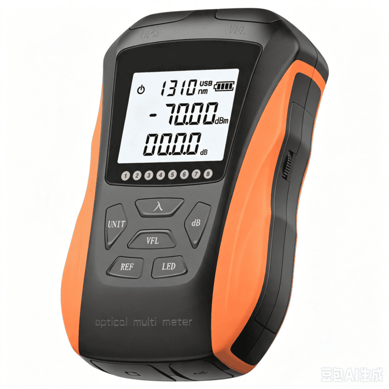
4-in-1 optical power meter with VFL combines optical power measurement and visible-light continuity checking in one handheld field instrument. It is intended for FTTH installation, maintenance and first-line troubleshooting where technicians need to verify received power, compare relative loss and visually locate accessible breaks or sharp bends without carrying several separate tools.
The term 4-in-1 describes a configuration family, not one universal function set. Optical power meter, 650 nm VFL, network-cable test, LED light, data storage, wireless transfer and rechargeable-battery options vary by selected SKU. LinkFiber therefore confirms the measurement range, calibrated wavelengths, red-light output, connector adapters, power supply and bundled functions on the quotation and approved datasheet.
Selecting the Correct 4-in-1 Configuration
Why a Combined Tester Still Needs a Controlled SOP
An integrated tester reduces tool count, but it does not remove measurement uncertainty. Before testing, clean and inspect connectors, select the calibrated wavelength, confirm the expected power range and allow the light source to stabilize. For relative loss, establish the reference with the same source, cords and adapters used for the measurement. Re-referencing after changing the test setup prevents cable and adapter loss from being hidden inside the result.
IEC 61315 provides a calibration framework for fibre-optic power meters, while IEC 61280-4-2 addresses attenuation and optical-return-loss measurement on installed single-mode cabling. Reference to these standards describes the measurement method; it does not mean every optional configuration is automatically certified. Calibration status, traceability and the exact acceptance method should be stated in the purchase order when they are contract requirements.
Technical Specifications
Function Boundaries and Measurement Limits
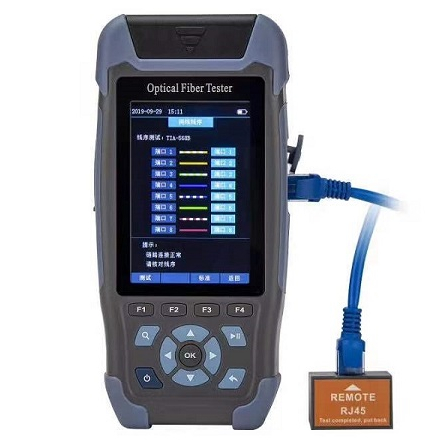
The OPM reports absolute optical power in dBm and, after a valid reference, relative loss in dB. It does not locate a fault by distance and it cannot separate individual splice or connector events. The VFL provides a visible indication for continuity, macrobends, breaks and poor accessible connections; it does not quantify insertion loss or certify a link. Network-cable, storage or wireless functions are supplementary and must be listed on the exact bill of materials.
A 0.01 dBm display step is resolution, not total measurement accuracy. Total uncertainty also depends on detector linearity, wavelength response, calibration, connector repeatability, reference stability and operator procedure. Procurement teams should avoid comparing instruments only by the smallest displayed digit.
Common Field-Failure Risks and Prevention
Pre-shipment Quality and Acceptance Plan
For B2B orders, LinkFiber can build a lot-specific inspection plan covering power-on test, detector response at agreed wavelengths, VFL output and mode, button and display operation, battery charging or battery-contact test, connector inspection, accessory completeness and label verification. Where measurement traceability is required, the order should define the reference instrument, calibration interval, test points, allowed deviation and report format before production.
- Confirm the exact SKU and function bundle against the signed datasheet.
- Check OPM response at the purchased wavelengths and at representative points within the selected range.
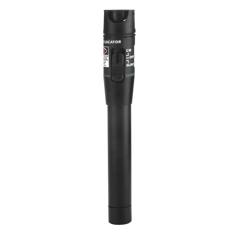
- Verify VFL wavelength, output option, CW/pulse operation and model-specific laser warning label.
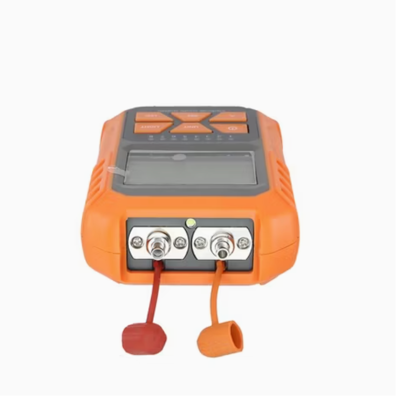
- Inspect the optical interface and supplied 2.5 mm/1.25 mm adapters for fit and cleanliness.
- Run a sample field workflow with the intended light source, cords and connector types.
- Record serial number, accessory list, firmware or manual version and packaging result when requested.
B2B Buyer Guide: Information Required for an Accurate Quote
To avoid receiving a tester that looks correct but cannot support the field workflow, provide the network type, expected optical-power range, wavelengths, connector interfaces, whether LC adapters are required, VFL output preference, desired auxiliary functions, power-supply preference, quantity, destination market and required documentation. For tenders, also state acceptance limits, calibration-report needs, label language and whether each technician kit requires a light source, cleaning tools or reference cords.
A practical purchasing comparison should evaluate measurement range, wavelength calibration, total uncertainty, port durability, battery support, accessory availability and repeatable inspection—not only the number of functions printed on the housing. A controlled standard model usually produces more consistent fleet results than several visually similar variants.
When to Choose Separate Instruments
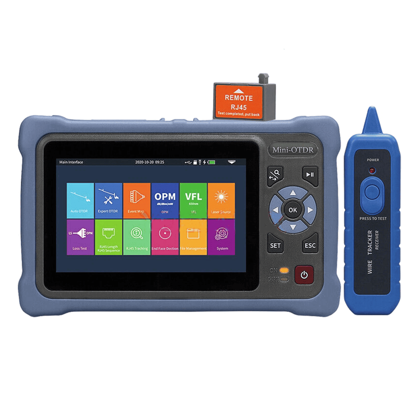
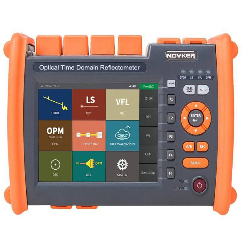
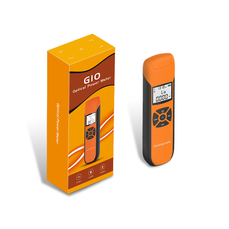
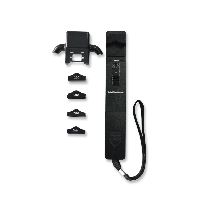
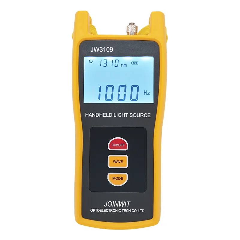
Choose separate instruments when higher traceability, independent calibration or simultaneous work is required. Pair a dedicated G10 optical power meter with a stabilized optical light source for controlled insertion-loss testing. Use a mini OTDR when the distance to a break, splice or reflective event must be located. Use an optical fibre identifier for non-destructive live-fibre checking before disconnection.
MOQ, Samples, Lead Time and Packing
Related Fiber Testing Tools
A complete FTTH field kit normally combines power/loss measurement, event location, live-fibre identification and connector cleaning. Review the Fiber Optic Testing Tools category to configure a consistent technician kit. LinkFiber can match instruments, adapters, reference cords and cleaning accessories to the project workflow and provide one consolidated packing list.
What is a 4-in-1 optical power meter with VFL used for?
How should B2B buyers choose the measurement range for a 4-in-1 optical power meter?
Why does VFL distance matter for a handheld optical power meter tester?
Can a 4-in-1 optical power meter with VFL replace an OTDR?
What should distributors confirm before bulk ordering 4-in-1 OPM VFL testers?
To learn more about this product, you can submit your requirements here.
 LF059 Handheld Fiber Optic Power Meter FTTH Network Cable Tester
 LF068 NK4000 Mini Pro 8-in-1 Smart OTDR
 LF063 Handheld OPM 4 in 1 Optical Power Meter With VFL
 LF-069-Professional Telecom Grade OTDR Optical Time Domain Reflectometer for Long Haul Fiber Cable Testing
 LF060 G10 Optic Power Meter Rechargeable USB with LCD Screen-High-Precision Fiber Tester
 LF-065-Telecom Grade Strong Light Fiber Optic VFL Waterproof Outdoor Cable Fault Locator
 LF-067-Mini Handheld Fiber Optic OTDR 1310/1550nm 24/22dB 60km Optical Time Domain Reflectometer FTTH Tester
 LF-071-Handheld Optical Fiber Identifier 800-1700nm Live Fiber Detector OFI Fiber Tester
 LF-072-Portable Fiber Optic Stabilized Light Source 1310/1550nm Handheld OLS FTTH Test Tool
 OTDR Fiber Extension Launch Cable Box
 LFW2 / W2S Mini Stable Optical Light Source
 LF064 Y8 Multifunction Optical Power Meter

Professional Consultation
If you are interested in our products and would like to know more details, please leave a message here, and we will get back to you as soon as possible.


