



‹
›
‹
›
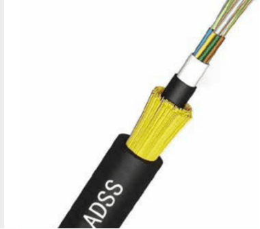
LF103 ADSS Fiber Optic Cable 4-144 Core Aerial Cable
ADSS cable:4/12/24/48/96/144 core
Outdoor jacket can be customized.
Share on





ADSS Fiber Optic Cable Engineering Guide for 4-144 Core Aerial Routes
ADSS fiber optic cable is an all-dielectric self-supporting aerial cable engineered to carry optical fibres between poles without a metallic messenger. It is used for telecom backbones, utility communication and overhead access routes where the cable must support its own weight under the specified span and environmental load. LinkFiber can formally supply 4-144 cores, but the correct design is selected from route data rather than fibre count alone.
An ADSS quotation should define the longest span, ruling span, sag, wind and ice conditions, installation tension, operating tension, electrical-field environment, sheath type and hardware. A statement such as “100 m span ADSS” is incomplete because two routes with the same pole spacing can require different aramid strength layers, cable diameters and anti-tracking performance.
Where ADSS Fiber Optic Cable Fits
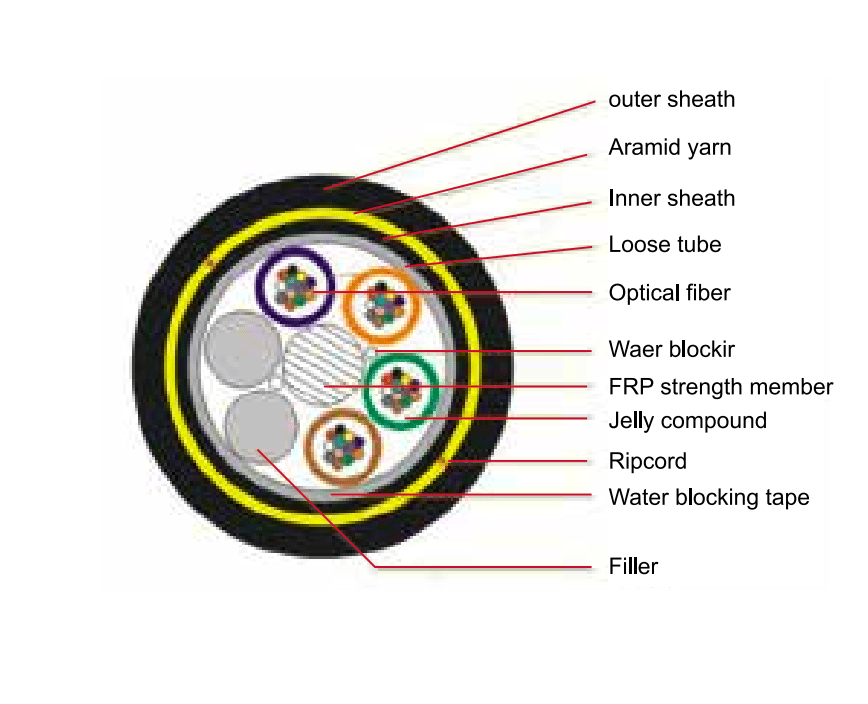
How the ADSS Construction Works
- All-dielectric means no metallic component: IEC 60794-4-20 covers ADSS cables with dielectric fibre units, strength members and sheaths. Figure-8 cables with metallic messengers are a different family and should not be described as ADSS.
- Loose tubes protect the fibres: fibres receive controlled excess length inside filled or dry water-blocked tubes so normal cable strain and temperature change are not directly transferred to the glass.
- FRP and aramid perform different jobs: a dielectric central member stabilizes the stranded core, while aramid yarn provides most of the tensile capacity. Yarn quantity must follow the mechanical design.
- PE and AT sheaths are not interchangeable labels: PE is commonly used on standard overhead routes. An anti-tracking sheath is selected when the electrical environment and utility specification require it; system voltage alone is not enough to select the sheath.
- G.652.D is the normal backbone choice: other fibre categories can be offered, but the fibre standard, attenuation acceptance and supplier documentation must be stated in the order.
Technical Specifications and Orderable Options
ADSS Route Engineering Decisions That Prevent Failure
Pre-shipment Quality and Acceptance Plan
- Construction verification: compare fibre count, tube layout, FRP, aramid layer, water blocking and sheath with the approved drawing.
- Optical test: verify continuity and attenuation at the agreed wavelengths with batch/reel traceability.
- Dimensional check: record cable diameter, sheath condition, metre mark, reel length and net/gross weight.
- Mechanical evidence: provide tensile, crush, bend, temperature or tracking evidence required by the contract.
- Reel release: confirm end sealing, test certificate, drum plate, rolling direction, packing and destination marks.
For repeat orders, the approved construction drawing, cable print, reel schedule and test-report template should be retained as controlled references. A generic model name is not sufficient evidence that a later batch uses the same fibre, tube layout, strength system, sheath or mechanical grade.
B2B Buyer Guide: Information Required for an Accurate Quote
- Fibre count, fibre category, colour code and optical acceptance values.
- Route drawing, span-by-span pole schedule, longest span and ruling span.
- Installation temperature, minimum/maximum operating temperature, wind and ice load.
- Required RTS, MAT, EDS, sag limit and safety factor or the utility design standard.
- Power-line voltage, cable position, electrical-field assessment and PE/AT sheath decision.
- Suspension, dead-end, vibration-control and down-lead hardware requirements.
- Reel length schedule, total quantity, cable print, destination and shipping limits.
- Required type tests, routine tests, certificates and report format.
When to Choose a Different Cable Construction
- Choose GYTC8S figure-8 cable when an integrated metallic messenger is required and grounding/corrosion controls are acceptable.
- Choose GYTA loose-tube cable for duct or supported/lashed outdoor routes that do not require self-supporting ADSS construction.
- Specify OPGW when the cable must function as an overhead ground wire; ADSS is not an OPGW substitute.
- Use a purpose-designed buried cable when the route is direct buried, rodent exposed or subject to severe crush.
MOQ, Samples, Lead Time and Packing
Related Cable and Network Components
Compare this ADSS design with GYTC8S figure-8 aerial cable, GYTA stranded loose-tube cable and GYXTW armored cable. Send the route profile, span table and load criteria so the cable and hardware can be checked as one system.
When is ADSS cable suitable for installation near power lines?
Can ADSS fiber optic cable be supplied up to 144 cores?
What should an ADSS pre-shipment inspection report include?
What is the difference between ADSS and GYTC8S figure-8 cable?
Which suspension and dead-end hardware should be ordered with ADSS cable?
What route data is required for an accurate ADSS quotation?
To learn more about this product, you can submit your requirements here.
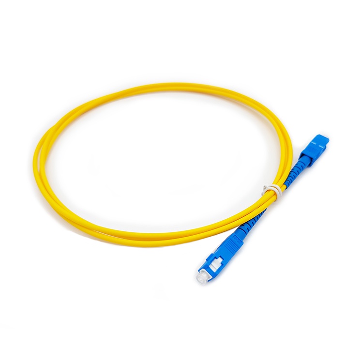
 LF005 Wholesale Optical Fiber Jumper Patch Cord Sc APC UPC 3M 2M 1M
 LF001 Single Mode G.657A SC UPC to SC UPC FTTH Drop Cable Fiber Patch Cord
 LF012 PLC PON Fiber Optic Splitter SC/LC/FC/ST for FTTH Solutions
 LF016 Mini PLC Fiber Optic Splitter Blockless Series 1×2/1×4/1×8/1×16
 LF020 Splice Pigtailed PLC Splitter ABS Box Single Mode FTTH Optical Coupler
![LF028 LC SC FC fiber optic adapter flange coupler for single mode multimode links]() LF028 LC/SC/FC Fiber Optic Flange Connectors Single Mode Multimode Fiber Optic Coupler
LF028 LC/SC/FC Fiber Optic Flange Connectors Single Mode Multimode Fiber Optic Coupler LF031Fiber Optic Pigtail Single Core & 12 Core Bundle 0.9mm 1.5m G.652D Single Mode
 LF009 Multimode Fiber Patch Cords OM3 SC LC 50/125μm Low Insertion
 LF022 Custom Split Ratio Non-uniform FBT Fiber Splitter 1310/1550nm Dual Window Low Loss
 LF025 FTTH Fiber Optic Aircraft Fast Connector
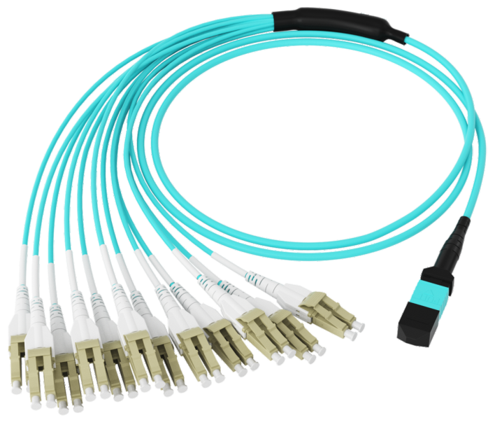
 LF104 High-Density MPO Patch Cable
 LF002 Single-mode Fiber Optic Patch Cord Simplex Duplex SC/FC/LC 2.0mm 3.0mm LSZH PVC

Professional Consultation
If you are interested in our products and would like to know more details, please leave a message here, and we will get back to you as soon as possible.


