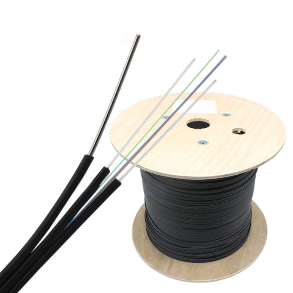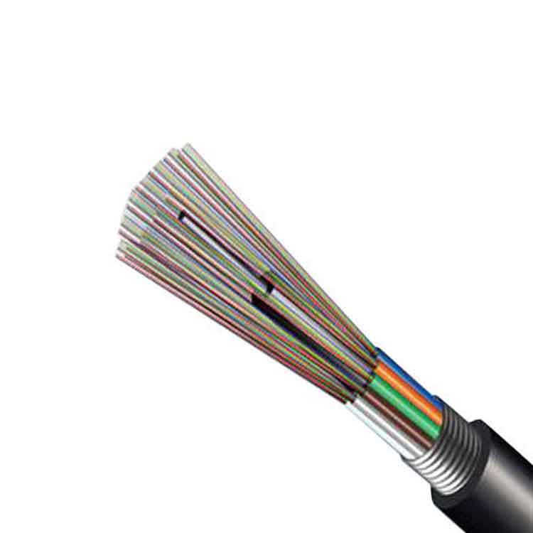


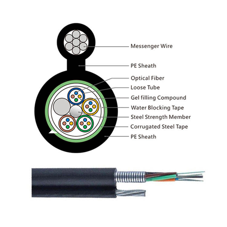
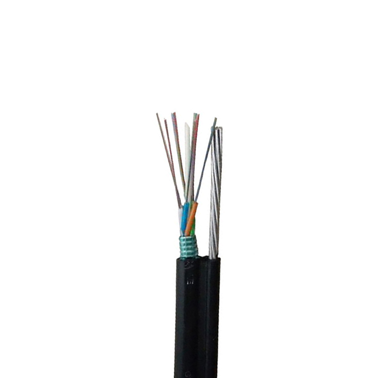
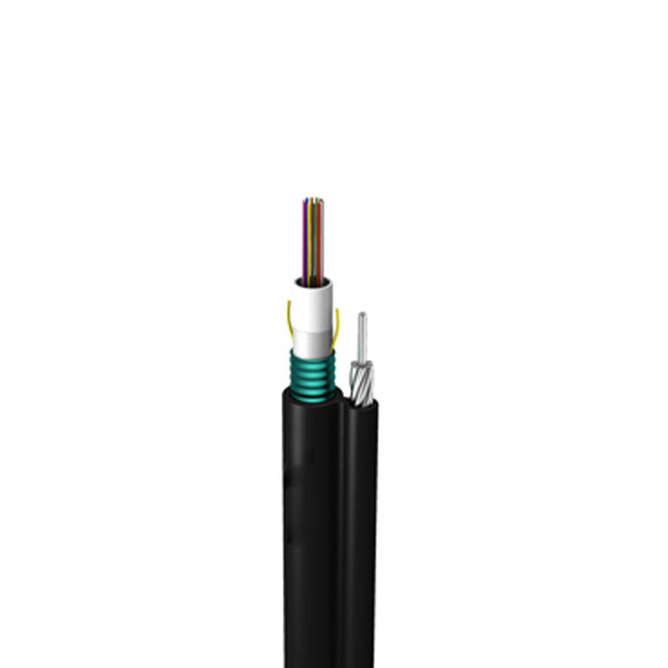
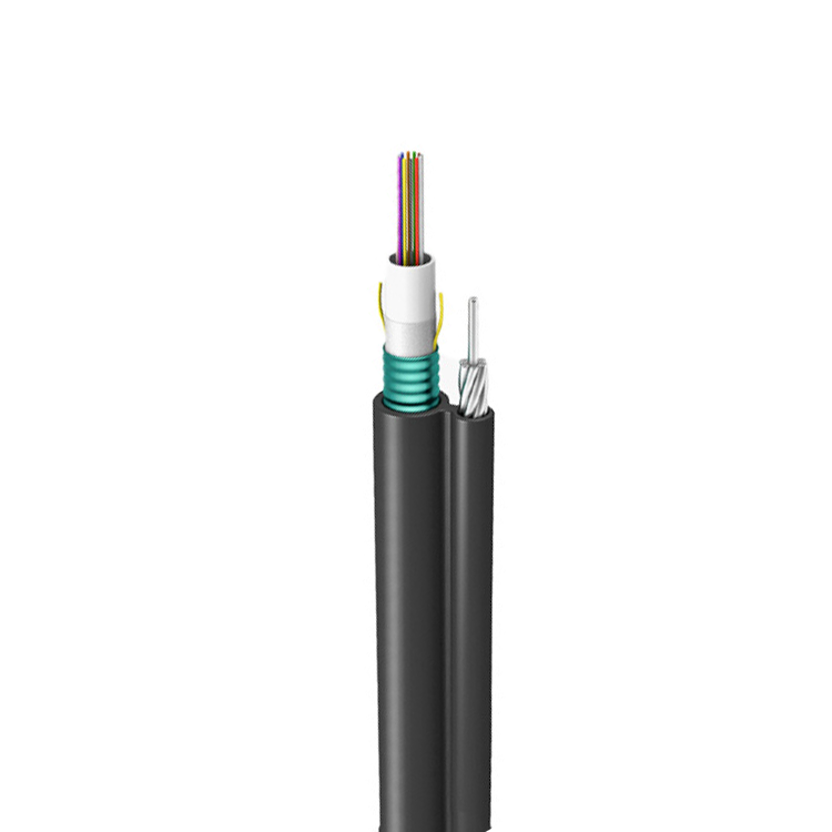
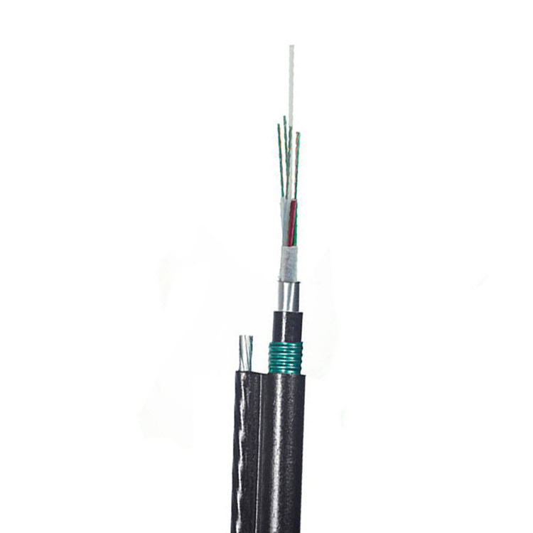
GYTC8S figure 8 fiber optic cable with integrated steel messenger

LF090 GYTC8S Figure 8 Fiber Optic Cable 2-144 Core

Available Specifications:

Fiber Count: 2, 4, 6, 8, 12, 24, 48, 72, 96, 144 Core 

Single-mode: G.652A / G.652D / G.657A1 / G.657B3

Structure: Figure-8 Self-Supporting, PSP Armored 

Custom fiber counts and span lengths available upon request.


Share on

Product Description

GYTC8S Figure 8 Fiber Optic Cable Guide for 2-144 Core Aerial Networks

GYTC8S figure 8 fiber optic cable combines an outdoor optical cable core with an integrated steel messenger in a self-supporting figure-8 profile. It is intended for pole-to-pole telecom routes, rural broadband and access/backbone distribution where a metallic messenger is acceptable. LinkFiber supplies 2-144 cores according to the selected loose-tube layout, messenger size and mechanical grade.

The messenger carries most of the aerial tensile load, while the optical cable portion provides fibre protection, water blocking and steel-tape mechanical protection. Core count does not determine span, tensile or crush performance by itself; the messenger diameter, steel grade, cable weight, pole spacing, wind/ice conditions and clamp system must be confirmed together.

Where GYTC8S Figure 8 Cable Fits

Route or project needWhy this construction fitsInformation required before quotation
Rural pole-to-pole broadbandIntegrated messenger reduces the need for a separate support strand.Pole spacing, terrain, wind/ice load and messenger requirement.
Outdoor access distribution2-144 core options can match feeder or distribution capacity.Fibre count, tube layout, splice closures and future capacity.
Short- to medium-span aerial routeSteel messenger supports the optical unit.Required span, sag, installation tension and clamp type.
Route needing steel-tape protectionArmored optical core improves mechanical protection.Required crush value, corrosion environment and water test.

Understanding the Figure 8 Cable Construction

  • Figure-8 is not ADSS: GYTC8S contains a metallic messenger. Electrical bonding, grounding, lightning exposure and corrosion must be considered where required by local practice.
  • The messenger and optical unit have different functions: the messenger carries aerial load; the loose tubes, central member, filling and armor protect the fibres.
  • Steel tape is not a substitute for route design: it improves mechanical protection but does not automatically make the cable suitable for direct burial or severe rodent exposure.
  • Fibre capacity changes the optical core: 2-144 core versions can require different tube/filler arrangements, diameters, weights and reel sizes. Approve the exact construction drawing.
  • Bending values follow the finished construction: a common planning reference is at least 10D static and 20D during installation, but the approved datasheet governs.

Technical Specifications and Orderable Options

ParameterOffered configurationProfessional procurement note
Product typeGYTC8S self-supporting figure-8 aerial optical cableIntegrated metallic messenger
Fibre count2-144 coresHigh-count construction drawing required before order
Fibre optionsG.652.D standard; G.657A1, G.655 or project fibre by confirmationSpecify attenuation and documentation
Optical coreStranded loose tubes around a central strength memberTube/filler layout varies by count
MessengerIntegrated steel messengerDiameter, construction and breaking load project-specified
ArmorCorrugated/plastic-coated steel tape around the optical unitConfirm coating, overlap and corrosion requirement
Water blockingTube filling and cable-core water blockingSpecify water-penetration test
Outer sheathOutdoor PE standard; other compounds by reviewConfirm UV, thickness and environmental exposure
InstallationSelf-supporting aerial pole routeNot an all-dielectric cable
Tensile strengthProject-specified by messenger, span and loadingDo not copy one value across all fibre counts and spans
Crush resistanceProject-specified armored outdoor gradeState N/100 mm long-/short-term values
Bend radiusCommon reference: static at least 10D; installation at least 20DFinal cable datasheet controls
Temperature rangeCommon outdoor design -40°C to +70°CConfirm exact model and test condition
Optical testingContinuity and attenuation at ordered wavelengthsReport per reel or agreed sampling
Diameter/weightBy fibre count, messenger and approved constructionNeeded for sag, clamps, reels and freight
Cable printMetre mark, model, fibre count and custom project printApprove marking draft
Reel lengthCustom by route and transport limitsCoordinate splice closure locations
AccessoriesSuspension/dead-end clamps and down-lead controls by routeHardware must match messenger and cable geometry
Standards/documentsIEC 60794-3 outdoor/aerial requirements and applicable YD/T; CE/RoHS/CPR where coveredConfirm exact scope, not only a generic certificate
CustomizationFibre count/type, messenger, armor, sheath, mechanical grade, print, reel and packingFinal specification follows approved drawing

Mechanical and Installation Decisions for GYTC8S

Decision or riskWhy it mattersControl before order
Messenger undersizedExcess sag or overload can occur under wind, ice or long spans.State span/loading and approve messenger breaking load.
Optical unit clamped instead of messengerLocal crushing or fibre attenuation can increase.Use hardware designed for the figure-8 geometry.
Metallic route risk ignoredLightning, induction, bonding or corrosion requirements may be missed.Apply local grounding and utility rules.
10D/20D used without final diameterAbsolute bend radius is calculated from the approved cable OD.Put diameter and bend radius in the order sheet.
Steel tape treated as burial armorSoil pressure, rodents and water may exceed the cable design.Use a burial-approved construction when required.
High-count design assumed identicalDiameter, weight and tube layout may change substantially.Approve the 48/96/144-core drawing and reel data.

Pre-shipment Quality and Acceptance Plan

  1. Construction check: verify messenger, loose tubes, central member, steel tape, water blocking and sheath against the drawing.
  2. Optical check: attenuation and continuity at agreed wavelengths, with reel/lot identification.
  3. Mechanical check: messenger and cable diameter, mass, tensile/crush evidence and bend requirement.
  4. Visual check: sheath, web between messenger/optical unit, print, metre mark and sealed ends.
  5. Packing release: reel length, drum size, gross/net weight, drum plate and export protection.

For repeat orders, the approved construction drawing, cable print, reel schedule and test-report template should be retained as controlled references. A generic model name is not sufficient evidence that a later batch uses the same fibre, tube layout, strength system, sheath or mechanical grade.

B2B Buyer Guide: Information Required for an Accurate Quote

  • Fibre count/type, tube colour code and optical acceptance.
  • Route length, pole spacing, longest span, sag and environmental loads.
  • Messenger material, diameter/strand construction and required breaking load.
  • Required tensile, crush, bend, water and temperature values.
  • Clamp/hardware system and installation method.
  • Steel-tape and sheath requirements, corrosion/UV environment.
  • Reel schedule, cable print, quantity, destination and unloading limits.
  • Test reports and certificates required by the operator or tender.

When to Choose a Different Cable Construction

  • Choose ADSS cable when the route requires a truly all-dielectric self-supporting design.
  • Choose GYTA cable for duct or separately supported/lashed routes.
  • Choose GYXTW cable for compact armored access routes where integrated aerial messenger is not required.
  • Specify a burial-rated armored design for direct-buried routes.

MOQ, Samples, Lead Time and Packing

Commercial itemStandard arrangement
MOQ1 km or project-based quantity; specifications can be customized according to customer requirements
SamplesAvailable according to customer requirements for construction, stripping, installation and optical approval
Lead timeNormally 5-10 days after the technical specification, cable marking and commercial terms are confirmed
PackingWooden reel, carton or project-specified export packing according to cable size and reel length
CustomizationFibre count, fibre type, construction, mechanical grade, sheath, reel length, printing, documents and packing

Related Cable and Network Components

Compare GYTC8S with ADSS all-dielectric cable, GYTA loose-tube cable and GYXTW armored cable. A route drawing and span table allow the messenger, hardware and reel schedule to be quoted accurately.

FAQ
Q:

Is the 100 m span guaranteed for every core count?

A:
No. It is a current reference maximum. Actual span depends on messenger size, cable weight, sag, wind/ice load, pole geometry and safety factors.
Q:

Can GYTC8S figure-8 cable be installed by direct burial?

A:
Standard GYTC8S is an aerial self-supporting construction with a steel messenger; it is not the default choice for direct burial. For buried routes, specify duct installation or a purpose-designed direct-burial cable with the required armor, water blocking and crush rating.
Q:

How is GYTC8S different from ADSS and lashed aerial cable?

A:
GYTC8S combines the optical unit with an integrated steel messenger in one figure-8 profile. ADSS is fully dielectric and self-supporting without a messenger; a lashed aerial cable relies on a separate support strand. Route electrical and hardware requirements differ.
Q:

What fibre counts and fibre types are available for GYTC8S cable?

A:
GYTC8S is available from 2 to 144 cores. G.652.D is the normal single-mode option, with G.657A1, G.655 or project fibre by confirmation. For high counts, approve the tube layout, diameter, weight, messenger and optical acceptance values.
Q:

What is the maximum span of GYTC8S figure-8 cable?

A:
There is no universal maximum span for every GYTC8S cable. Span depends on messenger size and grade, cable weight, sag, wind, ice, temperature and safety factor. Provide the pole schedule and loads so the messenger and clamps can be selected correctly.
Q:

What bending radius should be specified for GYTC8S cable?

A:
A common planning reference is at least 10 times the finished cable diameter in static service and 20 times during installation. The approved datasheet controls because fibre count, messenger and cable diameter can change the absolute radius.
Q:

How should tensile and crush values be specified for GYTC8S?

A:
Do not select values from fibre count alone. State long- and short-term tensile limits, long- and short-term crush in N/100 mm, the test method and route loads. The messenger, steel tape, cable diameter and high-count construction must match those acceptance values.
Inquiry

To learn more about this product, you can submit your requirements here.
Send Inquiry Now
Recommended Products