



‹
›
‹
›
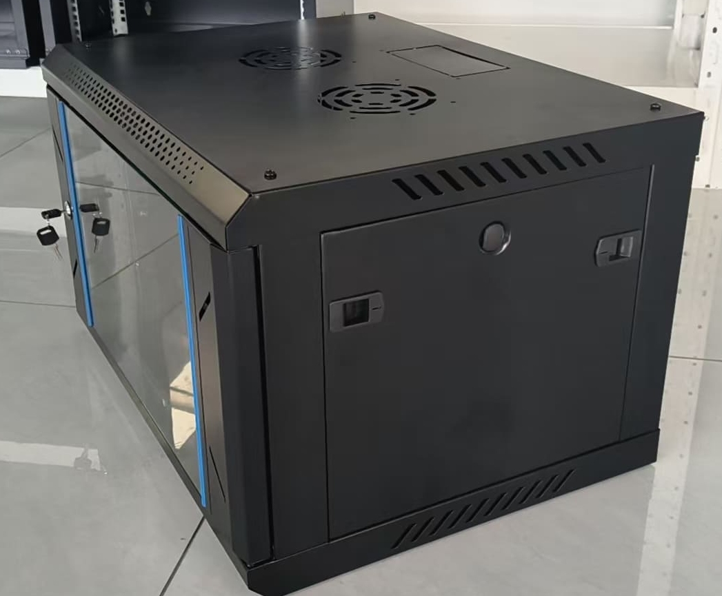
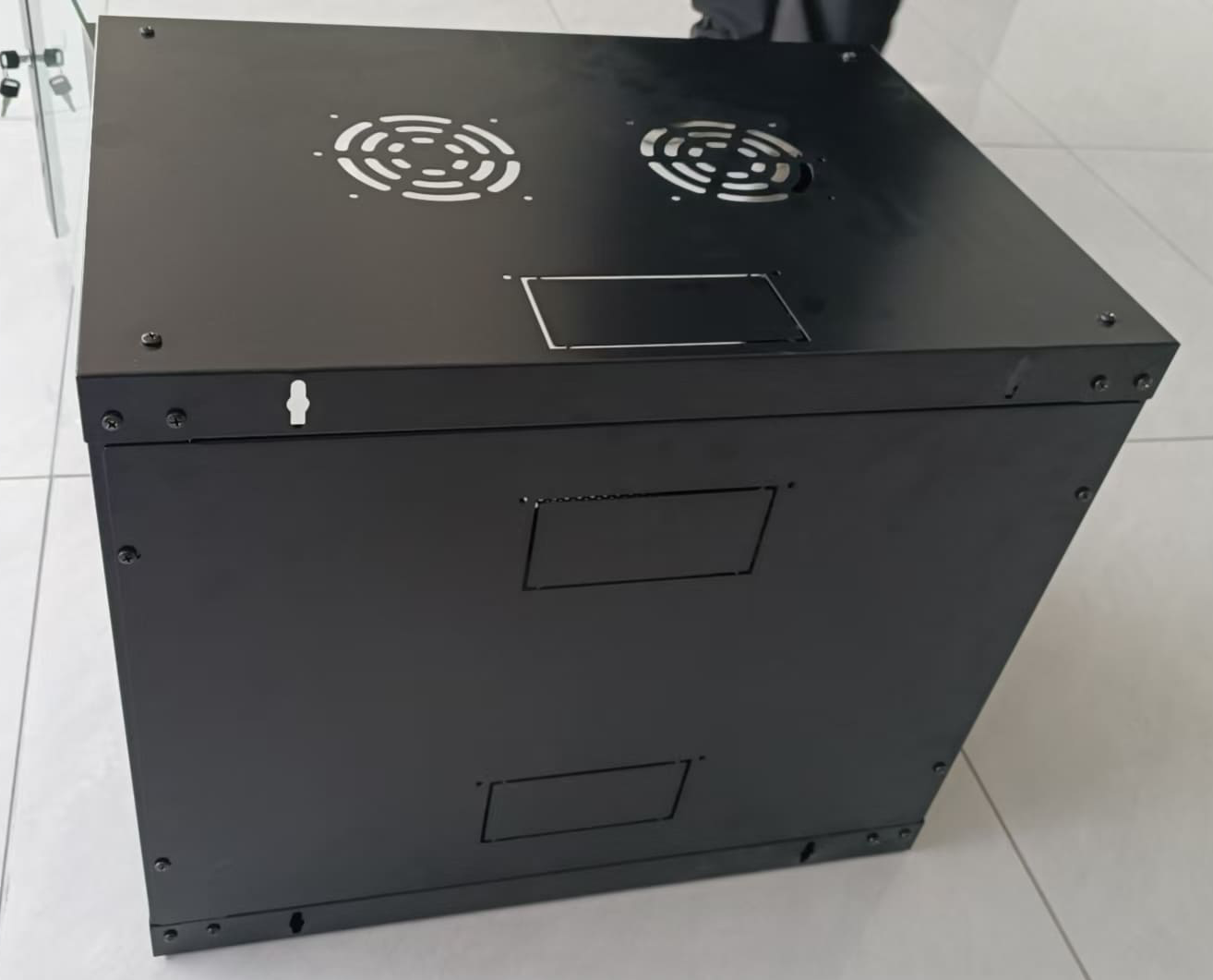
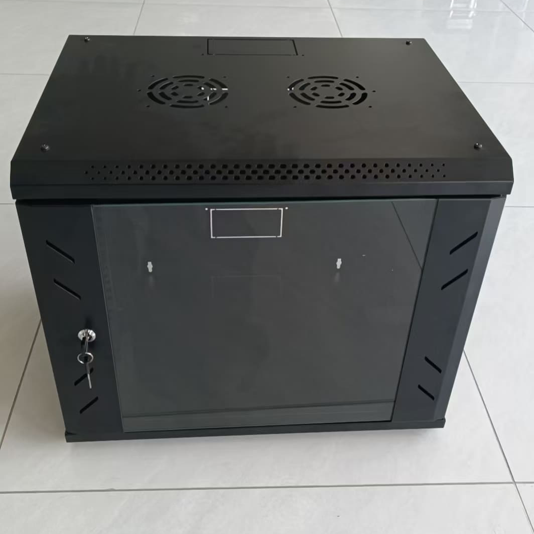
LF101 Wall Mounted Network Cabinet 4U/6U/9U/12U/15U/18U
Share on





19-Inch Wall Mounted Network Cabinet for 4U–18U Structured Cabling
The wall mounted network cabinet provides a compact 19-inch enclosure for patch panels, Ethernet switches, optical distribution units, cable managers and small power accessories. Correct selection starts with equipment depth, connector and cable bend clearance, total installed weight, wall substrate and thermal load—not rack-unit height alone.
This series covers 4U, 6U, 9U, 12U, 15U and 18U in 600×450 mm and 600×600 mm footprints. Door, sheet thickness, fan, PDU, shelf, cable-management and earthing options must be confirmed in one approved configuration.
Configuration and Project Selection
Technical Specifications
Rack Layout, Wall Loading and Thermal Planning
Prepare a front/rear rack layout before ordering. Add equipment depth, rear connector protrusion, copper bend allowance and optical fibre bend radius; then confirm total weight and centre of gravity. Fans do not solve restricted intake/exhaust paths, so door and vent selection must follow the actual heat load.
- Measure the deepest device including power plugs, SFPs and cable loops.
- Reserve U space for horizontal cable managers and service access.
- Confirm wall substrate and use engineer-approved anchors; drywall alone may be insufficient.
- Bond doors, frame and rack-mounted equipment where required by local rules.
- Separate power and data routing and protect fibre patch cords from door/hinge compression.
Common Procurement and Field Failures
Pre-shipment Quality and Acceptance Plan
Acceptance should cover dimensions, rack alignment, doors, locks, coating, hardware and the exact accessory BOM.
- Measure W×D×H and verify U marking and rail spacing.
- Check rail alignment, cage-nut fit, door operation, lock and removable panels.
- Inspect coating, edges, welds/fasteners and cable-entry openings.
- Verify fans, PDU, shelf, managers, brush panels and earthing parts.
- Perform representative static-load/fit checks where required.
- Photograph packing and protect glass doors and loose accessories.
B2B Buyer Guide: Information Required for an Accurate Quote
Send the following information before quotation:
- Required U height and 450/600 mm depth.
- Equipment list, deepest device, total installed weight and spare U.
- Wall material, installation height and permitted anchor method.
- Glass/mesh/metal door, lock and colour requirements.
- Fan quantity, PDU voltage/socket type, shelves and cable-management accessories.
- Assembled or knock-down delivery, logo, labels and packing requirements.
MOQ, Samples, Lead Time and Packing
Documentation and Compliance Boundaries
Load capacity, IP protection, CE/RoHS or fire-performance claims are model- and market-specific. They should not be inferred from cabinet dimensions; request evidence for the exact steel thickness, door, fan, PDU and supplied configuration.
Related Products and Project Interfaces
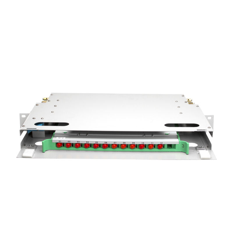
Use this cabinet with fiber distribution and management products, rack-mounted ODF/terminal boxes, patch panels, Ethernet switches and structured-cabling accessories.
What is a wall mounted network cabinet used for?
How should buyers choose between 4U, 6U, 9U, 12U, 15U and 18U wall cabinets?
Should a wall mounted network cabinet use 450 mm or 600 mm depth?
What should contractors check before installing a wall mounted network cabinet?
What options should distributors confirm before ordering wall mounted network cabinets in bulk?
To learn more about this product, you can submit your requirements here.
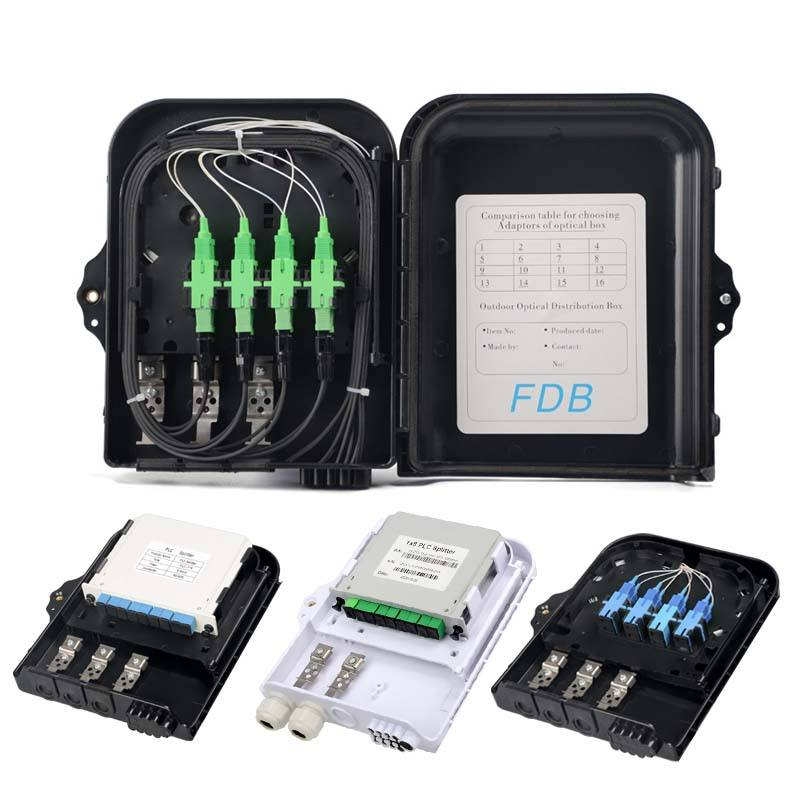
 LF076 Waterproof ABS FTTH Fiber Optic Distribution Box 8/16/24/32 Core FDB Splitter Cabinet
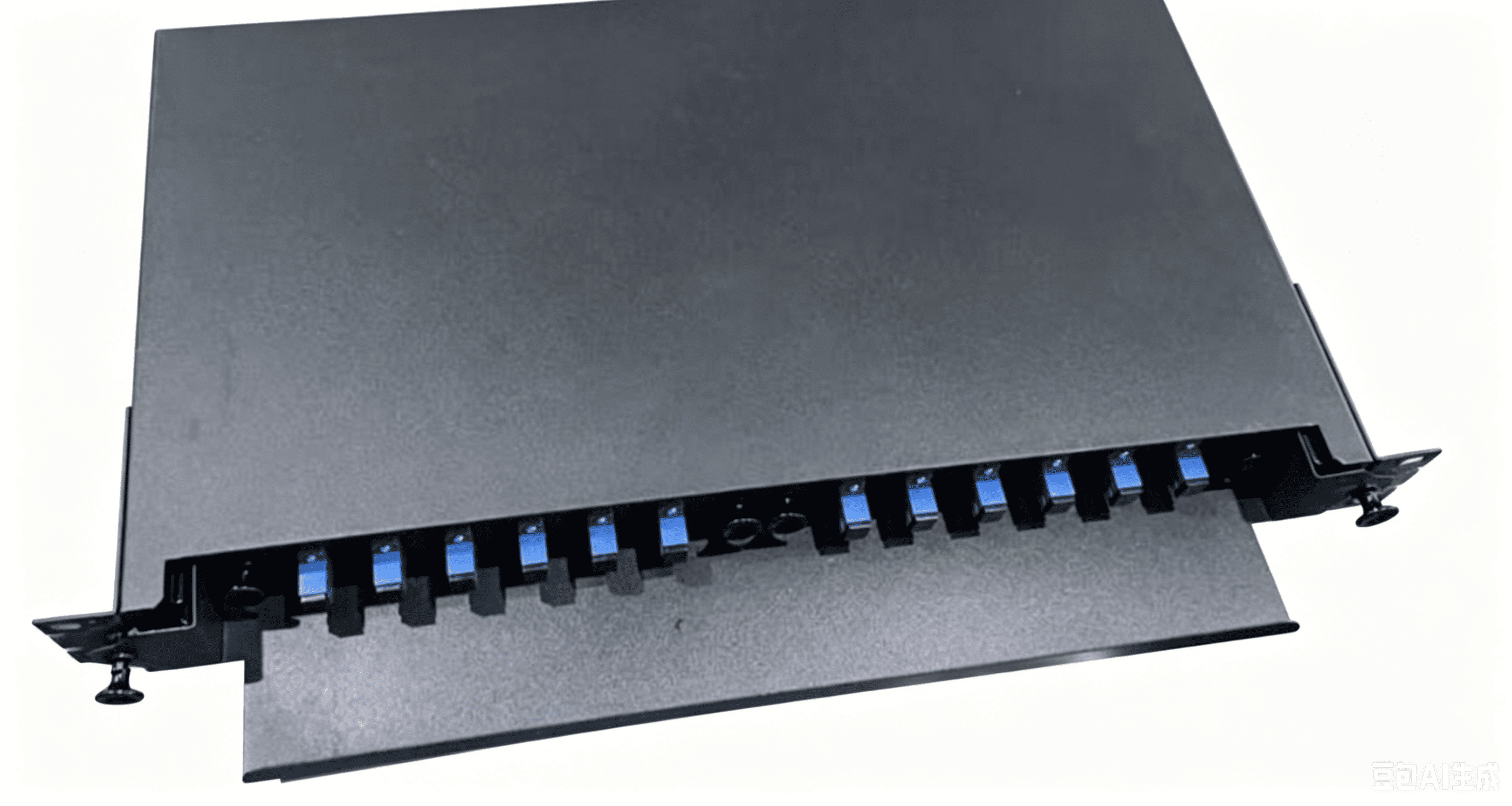
 LF080 OTB Sliding Fiber Optic Terminal Box Rack-mounted Enclosure
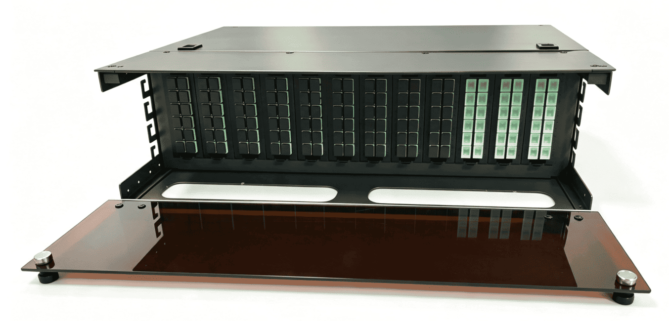
 ODF 288-Core High-Density Optical Distribution Panel
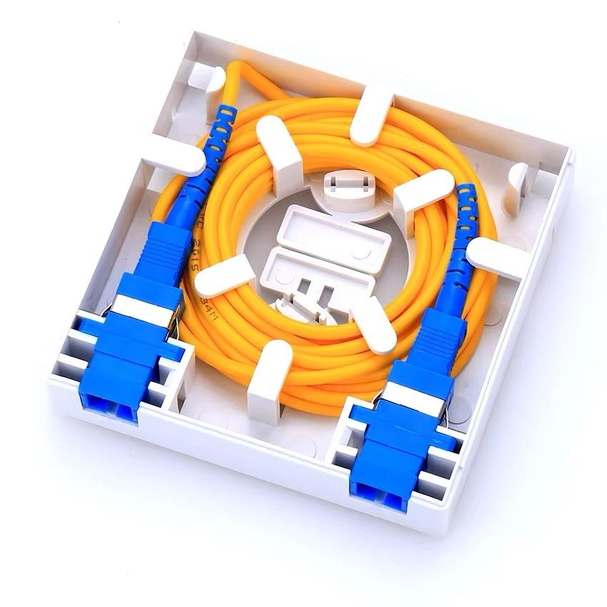
 LF-073-86 Type SC Simplex Fiber Optic Face Plate FTTH Wall Mount Outlet Indoor Junction Box
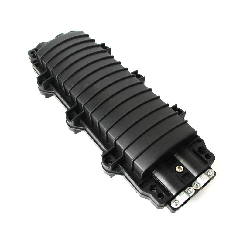
 LF074 IP68 Waterproof 24 Core Fiber Optic Splice Closure Horizontal Type Cable Joint Enclosure
 LF-085-Reinforced Metal Frame Slidable ODF Unit Telecom Grade Fiber Distribution Cabinet
 LF-086-Factory Custom SMC Outdoor Fiber Cabinet 96-1152 Core FTTH OCC Cabinet

Professional Consultation
If you are interested in our products and would like to know more details, please leave a message here, and we will get back to you as soon as possible.


