



‹
›
‹
›
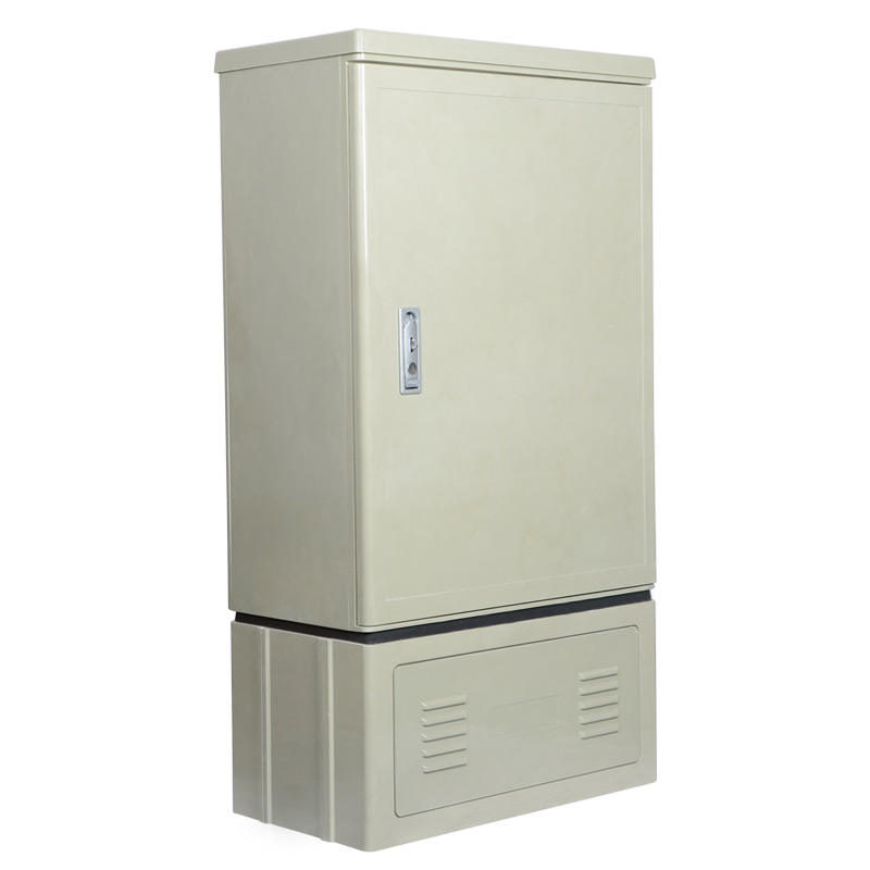
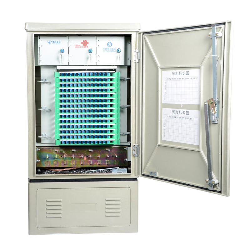
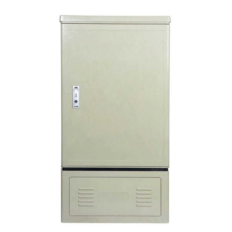
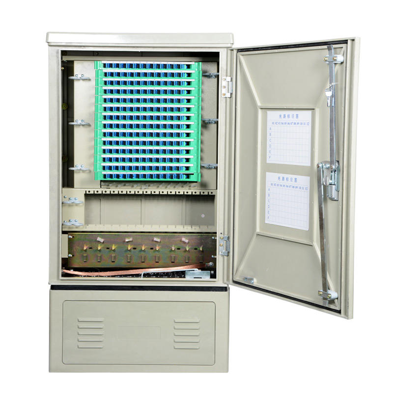
LF-086-Factory Custom SMC Outdoor Fiber Cabinet 96-1152 Core FTTH OCC Cabinet
Share on





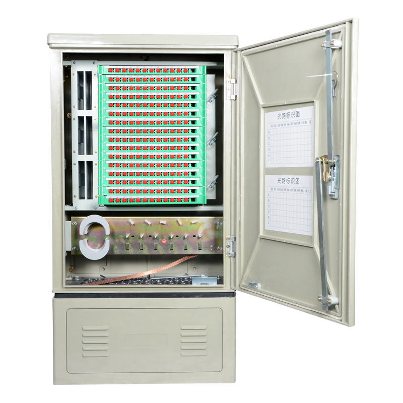
SMC Outdoor Fiber Optic Cross-Connection Cabinet for 96–1152 Core FTTH Networks
The SMC outdoor fiber cabinet is an optical distribution and cross-connection platform for feeder, distribution and splitter management in FTTH/ODN projects. Capacity alone is not a complete selection criterion: the approved design must also define adapter quantity, splice-tray loading, splitter parking, patch-cord routing, reserve-fibre storage, cable entry and safe technician access.
Published base configurations cover 96, 144, 288 and 576 cores. A 1152-core requirement is treated as a project-specific high-density or multi-bay configuration and should be released only after drawing, bill of materials, heat/space, cable-routing and maintenance-access approval.
Configuration and Project Selection
Technical Specifications
ODN Layout, Installation and Commissioning
Approve the fibre-routing drawing before production. Separate incoming-cable fixation, bare-fibre/splice storage and patch-cord management; reserve bend radius at every door, hinge and module transition. Site acceptance should inspect anchoring, seals, labels, grounding of metallic parts and end-to-end optical performance.
- Verify foundation or wall/pole load capacity and access clearance before delivery.
- Match every gland and unused-port plug to the actual cable OD and entry plan.
- Anchor sheath and strength members so cable tension does not reach trays or adapters.
- Clean and inspect connectors before mating; keep UPC and APC systems separated and labelled.
- Measure insertion loss/return loss according to the approved ODN test plan rather than attributing loss to the empty cabinet.
Common Procurement and Field Failures
Pre-shipment Quality and Acceptance Plan
Pre-shipment inspection should be based on the approved drawing and BOM, not on a generic cabinet photo.
- Check external dimensions, door alignment, lock operation, surface defects and mounting hardware.
- Verify adapter-panel, tray, splitter, gland and accessory quantities against the BOM.
- Perform routing and bend-radius inspection with a representative cable/patch-cord configuration.
- Check earth terminals and bonding parts where metallic components are included.
- Request exact-model enclosure/IP evidence when contractually required; evidence must cover the supplied configuration.
- Record labels, photos, packing list and lot inspection results before shipment.
B2B Buyer Guide: Information Required for an Accurate Quote
For an accurate quotation and usable cabinet design, provide:
- Required core/port count and feeder/distribution/splitter topology.
- Connector type and polish: SC/LC/FC, UPC or APC.
- Splitter ratios, module style and quantity.
- Incoming/outgoing cable construction, count, OD and entry direction.
- Installation method, foundation/base/pole/wall details and available clearance.
- Outdoor environment, target IP level and any corrosion/UV requirements.
- Accessories, labelling, logo, documentation, inspection and packing requirements.
MOQ, Samples, Lead Time and Packing
Documentation and Compliance Boundaries
IP65, CE, RoHS, flame-retardant or other compliance statements should be published only when the exact ordered cabinet and material configuration are covered by valid evidence. IEC 60529 describes enclosure IP testing, but it does not make every cabinet installation automatically IP65.
Related Products and Project Interfaces
Coordinate the cabinet with fiber distribution products, outdoor splice closures and project-specific PLC splitters, adapters, pigtails and patch cords.
What are the MOQ, lead time and packing options for custom SMC fiber cabinets?
What information is needed for an accurate SMC outdoor fiber cabinet quotation?
How can overseas buyers inspect an outdoor fiber cross-connect cabinet before shipment?
Does an SMC outdoor fiber cabinet need grounding, and how should it be installed?
What should buyers verify before ordering an IP65 outdoor fiber cabinet?
Can the SMC fiber cross-connect cabinet support SC/APC, SC/UPC and PLC splitters?
Should distributors order an empty or fully equipped FTTH OCC cabinet?
How do I choose the right capacity for an SMC outdoor fiber optic cabinet?
To learn more about this product, you can submit your requirements here.
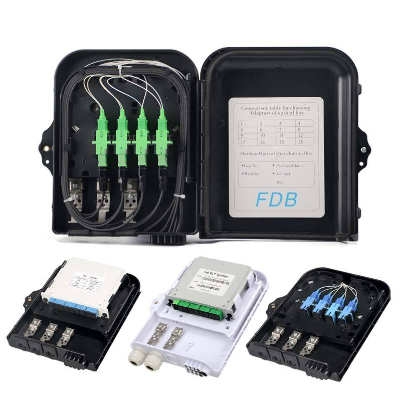
 LF076 Waterproof ABS FTTH Fiber Optic Distribution Box 8/16/24/32 Core FDB Splitter Cabinet
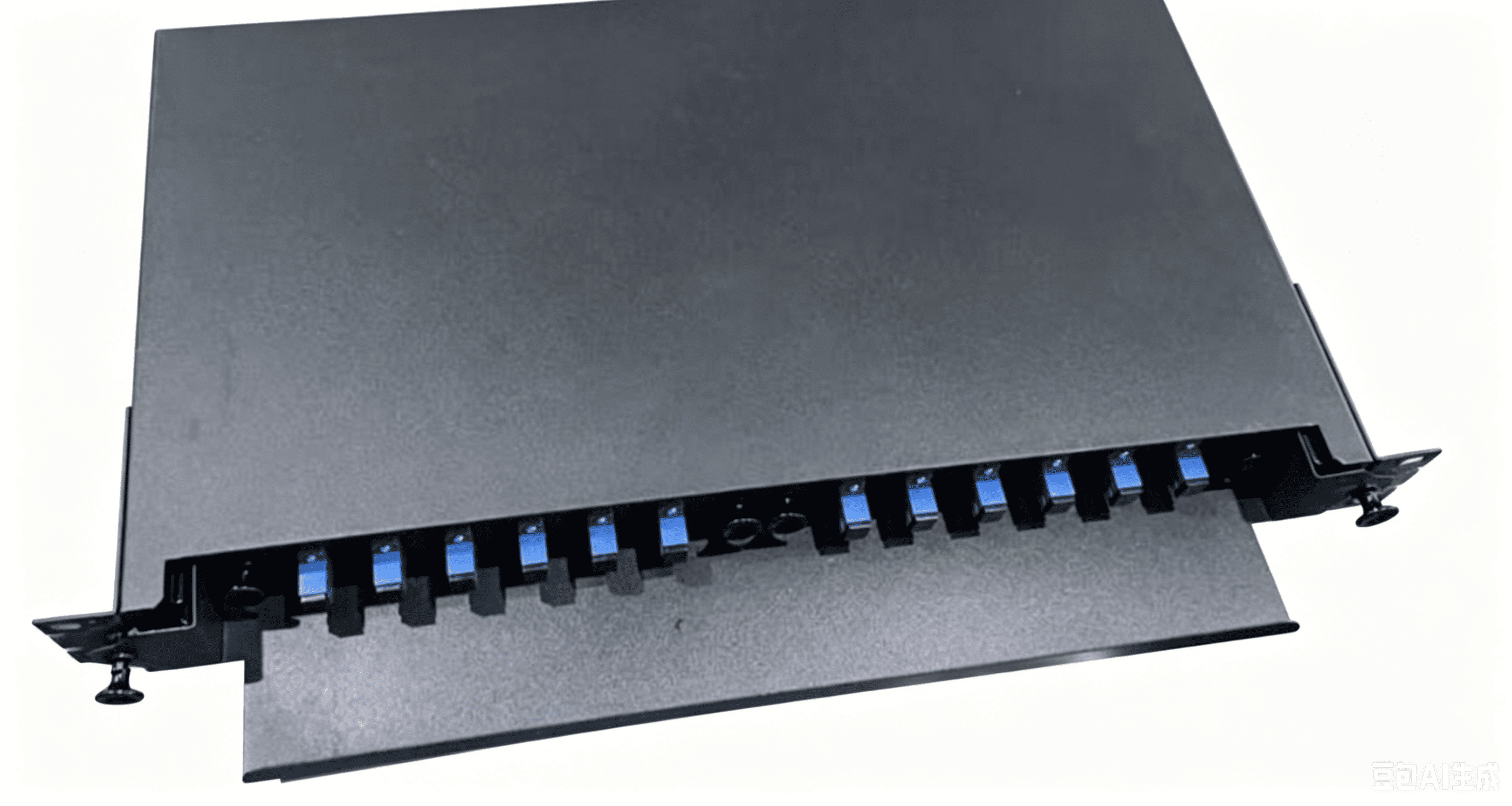
 LF080 OTB Sliding Fiber Optic Terminal Box Rack-mounted Enclosure
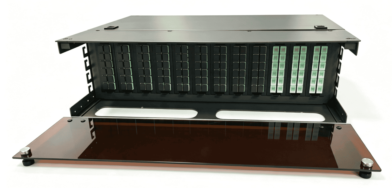
 ODF 288-Core High-Density Optical Distribution Panel
 LF-073-86 Type SC Simplex Fiber Optic Face Plate FTTH Wall Mount Outlet Indoor Junction Box
 LF074 IP68 Waterproof 24 Core Fiber Optic Splice Closure Horizontal Type Cable Joint Enclosure
 LF-085-Reinforced Metal Frame Slidable ODF Unit Telecom Grade Fiber Distribution Cabinet
 LF-086-Factory Custom SMC Outdoor Fiber Cabinet 96-1152 Core FTTH OCC Cabinet

Professional Consultation
If you are interested in our products and would like to know more details, please leave a message here, and we will get back to you as soon as possible.


