



‹
›
‹
›
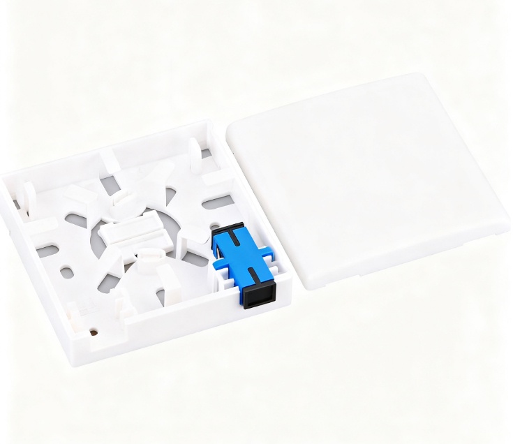
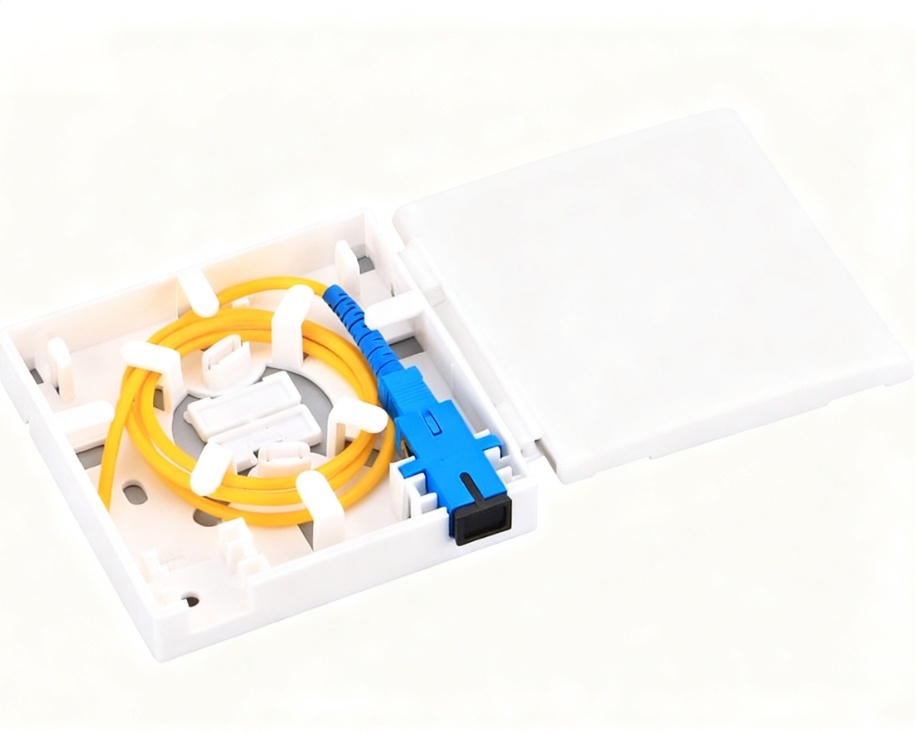
LF-073-86 Type SC Simplex Fiber Optic Face Plate FTTH Wall Mount Outlet Indoor Junction Box
Share on





86 Type Fiber Optic Face Plate for FTTH Indoor Termination
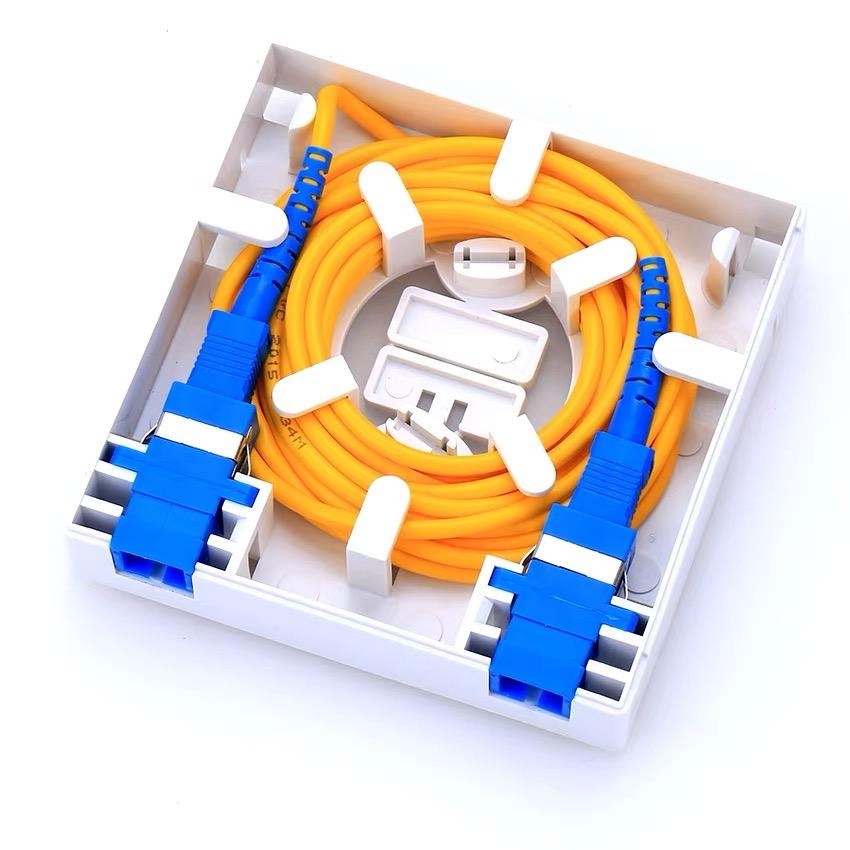
86 type fiber optic face plate provides the final indoor termination point between FTTH drop cable and the subscriber patch cord. It should protect the adapter, splice or field connector, maintain fibre bend radius and transfer cable pull force to the housing rather than the optical connection.
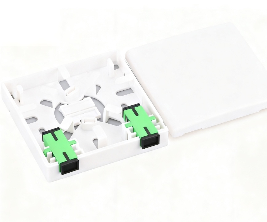
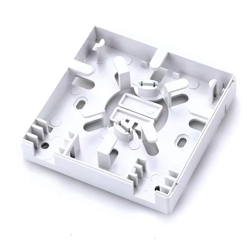
The SC simplex version is the primary configuration, while port count, LC/FC footprints, UPC/APC interface, adapter, pigtail and mounting accessories are project-specified. The empty plastic box does not determine optical loss; the complete connection path and workmanship do.
Configuration and Selection Guide
Indoor Termination Architecture
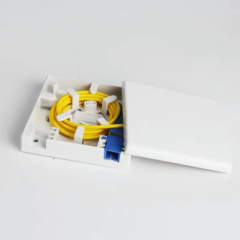
For fusion termination, the box must store the sleeve and fibre slack without crossing sharp edges. For a field connector, allow assembly space and verify connector boot length. Pre-terminated drops reduce field work but require protection during pulling. Confirm whether the order includes only the face plate or a complete kit with adapter, pigtail, sleeve and screws.
Technical Specifications
Optical Performance Boundaries
Insertion loss and return loss belong to the adapter/connector path and must be measured with clean reference cords at the specified wavelength. APC and UPC interfaces are mechanically similar but optically incompatible. A face plate must not be marketed as guaranteeing ≤0.2 dB unless the supplied adapter, connectors and test method are included in the acceptance plan.
Cable Retention and Bend Management
Anchor the drop-cable jacket and strength members before exposing fibre. Route G.657.A fibre around smooth guides, keep the splice sleeve in its holder and confirm that closing the cover does not pinch the fibre. Pull-out performance depends on the actual clamp and cable; verify the stated force on the selected configuration.
Common Installation Risks and Prevention
Pre-shipment Quality and Acceptance Plan
Lot inspection can verify dimensions, port footprint, cover fit, screw set, cable entry, adapter retention, splice-sleeve storage, fibre routing and material/label consistency. For complete kits, test insertion loss and return loss on a defined sample using the ordered UPC/APC components.
- Approve an assembled sample, not only an empty housing.
- Confirm adapter footprint, polish and dust caps.
- Test the real drop cable in the clamp.
- Close the cover with full slack and sleeve storage.
- Check moulding, latch, screw bosses and sharp edges.
- Match all compliance documents to the exact material and configuration.
B2B Buyer Guide: Information Required for an Accurate Quote
Provide port count, adapter type and polish, cable dimensions, termination method, pigtail length/fibre type, sleeve type, mounting box standard, quantity, label/logo, destination and documentation requirements. State whether each unit must be preassembled and individually tested.
MOQ, Samples, Lead Time and Packing
Related Distribution Products
Compare Fiber Wall Boxes, Optical Terminal Boxes and Optical Distribution Boxes to match subscriber, floor and building-level capacity.
What is an 86 type SC simplex fiber optic face plate used for?
How should buyers choose UPC or APC for an SC fiber optic face plate?
Why do bend radius and strain relief matter in an FTTH wall mount outlet?
Should buyers choose a field connector, fusion-spliced pigtail or pre-terminated drop cable?
What should distributors confirm before ordering FTTH fiber optic face plates in bulk?
To learn more about this product, you can submit your requirements here.
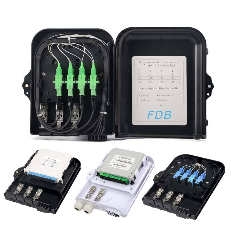
 LF076 Waterproof ABS FTTH Fiber Optic Distribution Box 8/16/24/32 Core FDB Splitter Cabinet
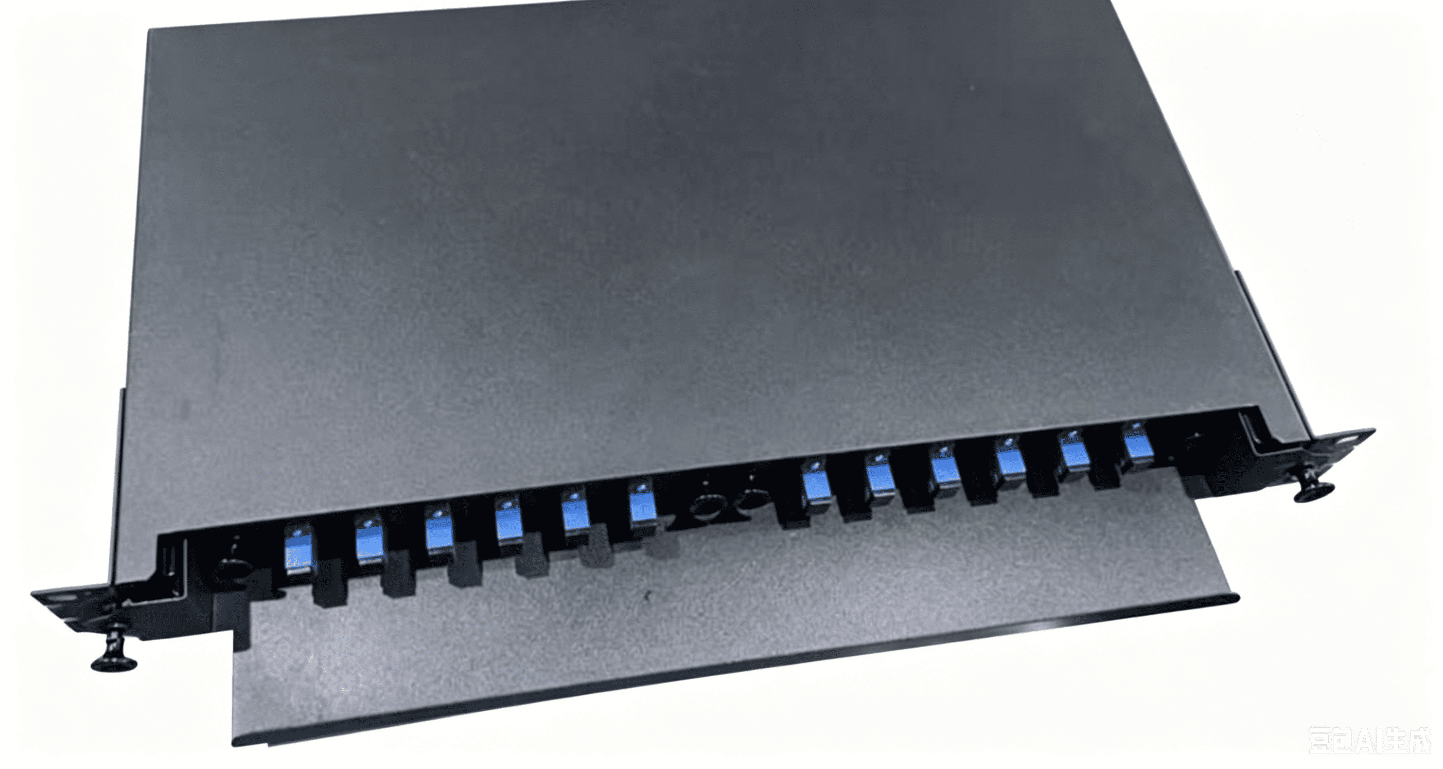
 LF080 OTB Sliding Fiber Optic Terminal Box Rack-mounted Enclosure
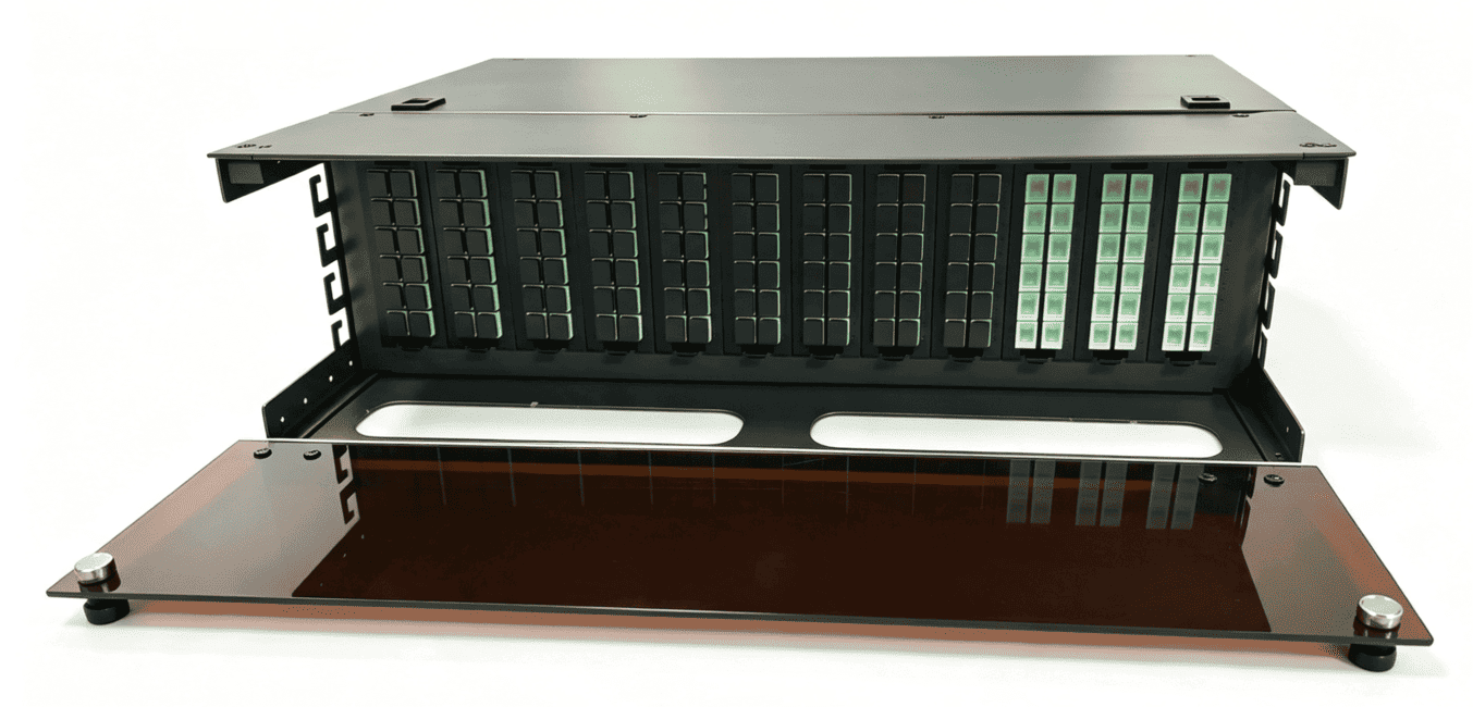
 ODF 288-Core High-Density Optical Distribution Panel
 LF-073-86 Type SC Simplex Fiber Optic Face Plate FTTH Wall Mount Outlet Indoor Junction Box
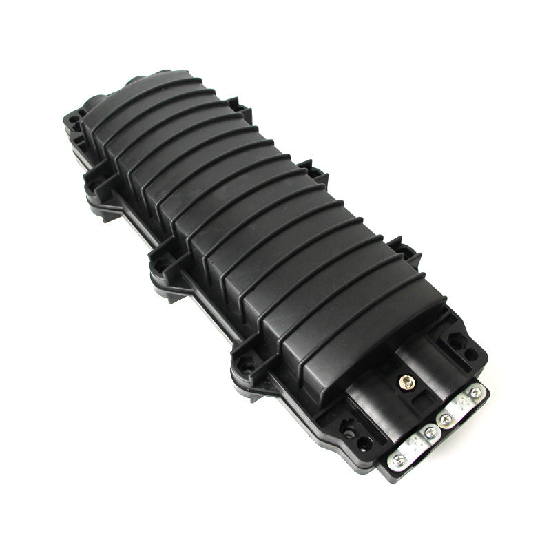
 LF074 IP68 Waterproof 24 Core Fiber Optic Splice Closure Horizontal Type Cable Joint Enclosure
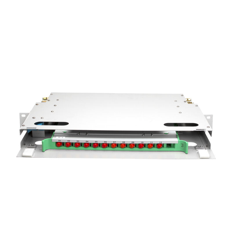
 LF-085-Reinforced Metal Frame Slidable ODF Unit Telecom Grade Fiber Distribution Cabinet
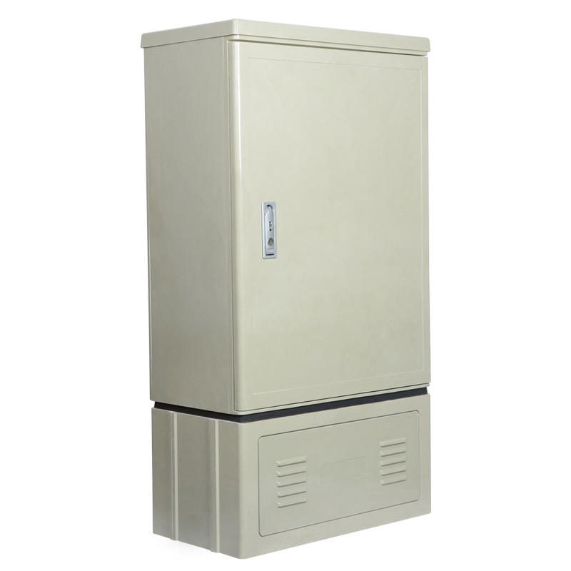
 LF-086-Factory Custom SMC Outdoor Fiber Cabinet 96-1152 Core FTTH OCC Cabinet

Professional Consultation
If you are interested in our products and would like to know more details, please leave a message here, and we will get back to you as soon as possible.


